← Back to Projects
EmbeddedShippedFeatured

Vend-A-Shoe

Designed and shipped a client-facing electromechanical dispensing platform integrating mechanical packaging, embedded control, and cloud-connected automation.

During my internship at BrainChild Engineering, I developed Vend-A-Shoe for a client deployment. The work meant designing a custom mechanical enclosure; integrating electrical distribution for 4 MG996R servos, 8 LED indicators, and a cooling fan across 40+ wire interconnects; writing embedded control on a Raspberry Pi; and connecting that stack to an existing frontend through a cloud command pipeline. The hardest part was not any single subsystem; it was integrating them. Packaging moved the harness; electrical changes moved the enclosure; software had to absorb real manufacturing tolerances.

Engineering highlights

  • Designed a custom enclosure with 3D-printed fixtures and laser-cut panels for manufacturable assembly
  • Integrated 4 MG996R servos, 8 LEDs, and a fan through a centralized power-distribution architecture with Raspberry Pi GPIO control
  • Merged a new backend with an existing production frontend for remote cloud-triggered dispensing
Date
Summer 2026
Focus
Electromechanical Systems
Build stage
Client Deployment
Disciplines
Mechanical Design · Electrical Integration · Embedded Systems · Cloud Software
Raspberry Pi 4PythonNext.jsSupabaseMG996ROnshapeGPIOPWMUSB-C PDLEDsfanmultimetersystemd
Phone trigger to physical dispense

Phone trigger to physical dispense

Full write-up below. The hero is the short version. This is the build story: what I designed, what broke, and why I made the calls I did.

Motivation

Why I started this

What pulled me in, and what I wanted to get better at.

Why I built it

I built this at BrainChild Engineering for a client who needed a unit that could leave the lab. A breadboard demo was never the finish line.

What interested me

BloomBot got me comfortable with servos on Arduino. This one stacked packaging, a dense harness, power distribution for motors plus eight LEDs and a fan, and a Pi that had to stay alive on a wall adapter; that mix is what pulled me in.

What I wanted to learn

I wanted sharper instincts for debugging across systems, not inside one tidy layer. Mechanical clearance, rail voltage, GPIO maps, and queue state fail together; the useful skill is deciding which system to trust first, then proving it with a supply and a meter instead of rewriting code on a guess.

System Overview

How the system fits together

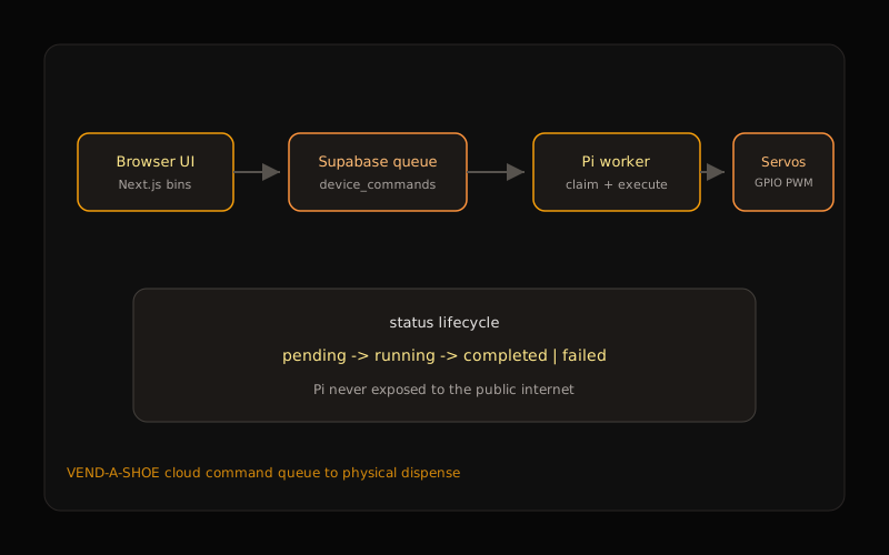
A Next.js dashboard drops bin dispense commands into Supabase. A Raspberry Pi worker claims each row, drives MG996R servos off a soldered protoboard that also feeds eight LEDs and a cooling fan, then writes completed or failed. The harness was the product as much as the queue was; enclosure, power, and dozens of connections were in the loop from the start.

01

Enclosure & mounts

Onshape assembly with printed mounts, wire covers, and a laser-cut rear panel you can actually open again.

02

Power & protoboard

Wall AC to DC / USB-C PD into a soldered protoboard with common ground; one outlet path feeds servos, eight LEDs, the fan, and the Pi.

03

Harness

Forty-plus wires for motors, LED runs, fan, and control; lengths and service loops were design constraints, not cleanup.

04

Pi worker

Python process claims pending commands, maps bin to GPIO, runs PWM sweeps, persists status.

05

Command queue

Supabase device_commands with pending to running to completed or failed; the Pi never needs a public port.

06

Dashboard

Existing frontend kept in place; the new backend had to meet its API shape and show queue state clearly.

Data flow

UI insert; Supabase queue; Pi claim; GPIO and PWM; servos plus eight LEDs plus fan; status write-back.

Control flow

Only the worker owns actuation. The browser never talks to GPIO; claiming by status update keeps two polls from firing the same dispense.

Control path
Vend-A-Shoe system architecture

Dashboard to queue to Pi to protoboard to servos, LEDs, and fan.

At a Glance

Shipped, hard parts, next revision

What shipped

Assembled, wall-powered unit with enclosure, dense harness, Pi worker, and cloud-queued multi-bin dispense delivered to the client.

What made it hard

Cross-layer failures (fried motors, DHCP/SSH loss, bad joints, overvoltage) shared the same “it doesn’t work” symptom until meters and substitution isolated the layer.

What changes next

KiCad distribution board with keyed connectors and branch protection, closed-loop dispense sensing, and a Version 2 sequence that freezes power and harness before packaging.

Timeline

How the summer actually went

June 11 to July 28. Part-time, with one travel week in the middle (July 18–25). Dates below are reconstructed from notes and media.

  1. June 11–17

    Pi bring-up, GPIO/PWM learning, first motor experiments, breadboard and bench-supply basics.

    What slowed it: New platform, unknown whether the motors were even good, no EE mentor in the room.

  2. June 18–25

    Early end-to-end path that became fullvideoinitialdemo.mp4: one-motor / two-LED app demo, then more motors as replacements came online.

    What slowed it: Several motors were already dead. I kept rebuilding the circuit before a swap test proved the hardware was the problem.

  3. June 23–30

    All four motors working with the app on breadboard; fan in the loop; started moving toward protoboard and wire-length planning.

    What slowed it: No protoboard in stock at first. Soldering tools were rough: dull iron, paste instead of wire, no fume extraction.

  4. July 1–7

    Most wiring soldered and labeled; protoboard mounted; diagnosed SSH loss after a Wi-Fi reset changed the Pi's DHCP address; isolated a bad fan joint by substitution.

    What slowed it: Dynamic IP, borrowed-monitor dependency, dense harness rework.

  5. July 8–15

    Wire bundling, CAD rear cover, wire covers, mounting, Pi screw-terminal connector, packaging for transport and service.

    What slowed it: I had already cut wire lengths before the layout fully froze, so the enclosure had to adapt to the harness.

  6. July 18–25

    Only travel week. While I was away, a 24 V connection likely damaged motors. The team chased faults, including a failed alligator clip; replacements arrived.

    What slowed it: That overvoltage mistake was mine. Recovery was slower because there was almost no power-review process or spare-qualified actuators ready.

  7. July 27–28

    Finalized USB-C PD / wall power, corrected LED color mismatch, cleaned up soldering and wire management, got all four motors / eight LEDs / fan running for the client demo.

    What slowed it: Too much of the last validation still sat at the deadline.

Engineering Breakdown

Broken down by discipline

Each block covers the goal, the design, what broke, what changed, and what shipped.

01Mechanical

Mechanical

Goal

Fit the dispense mechanism, Pi, protoboard, fan, and a dense harness in a compact box that still opens for service.

Design

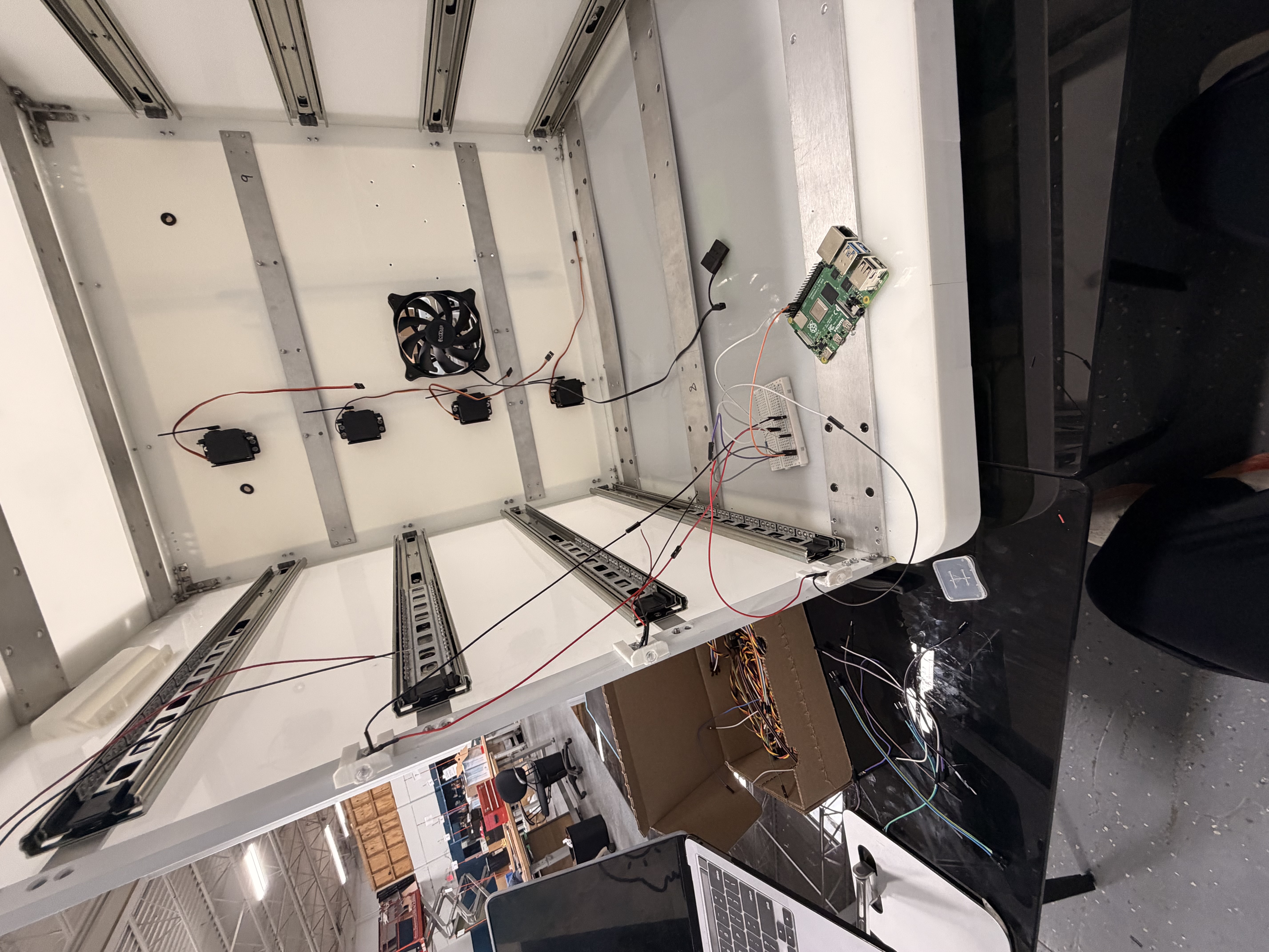
Custom Onshape enclosure; printed mounts and extenders; laser-cut rear panel. Clearances and harness paths for motors, eight LEDs, and the fan drove the layout more than the outer silhouette did.

Challenges

  • Four servo positions plus LED runs and a fan left almost no slack once the harness existed.
  • Eight LEDs needed unique lengths; four per side at different heights.
  • Wire lengths got cut before the mounting layout froze, so service access and cover clearance became a fight with a forty-plus-wire bundle.

Iterations

  • CAD packing against real component envelopes, including fan clearance.
  • Print, fit, remount cycles on brackets, covers, and extenders.
  • Rear panel cut so cables and rework did not mean a full teardown.

Final implementation

Integrated mounts, organized routing, removable rear panel. It shipped as one assembly, not a pile of boards in a shell.

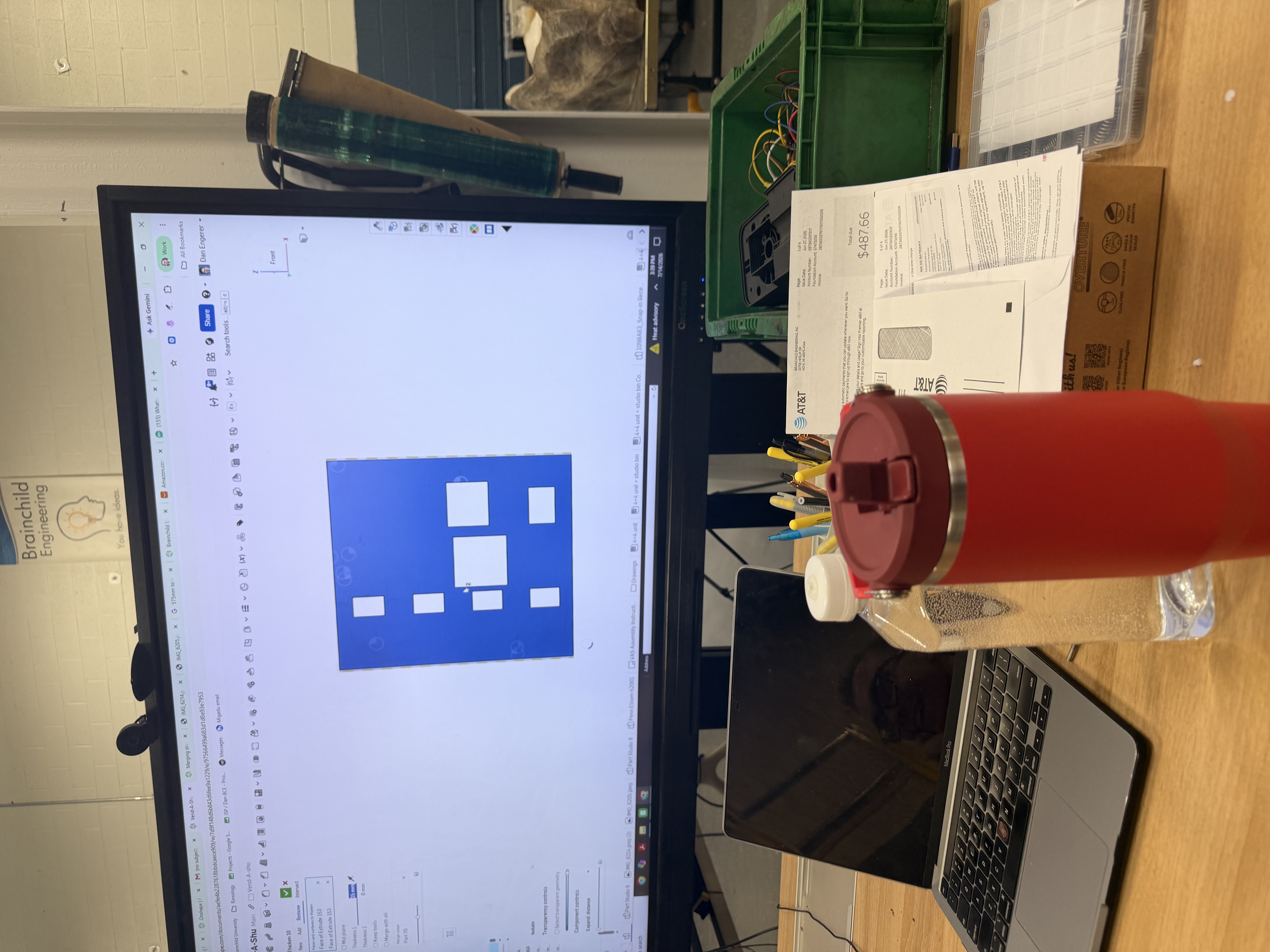
Full enclosure CAD
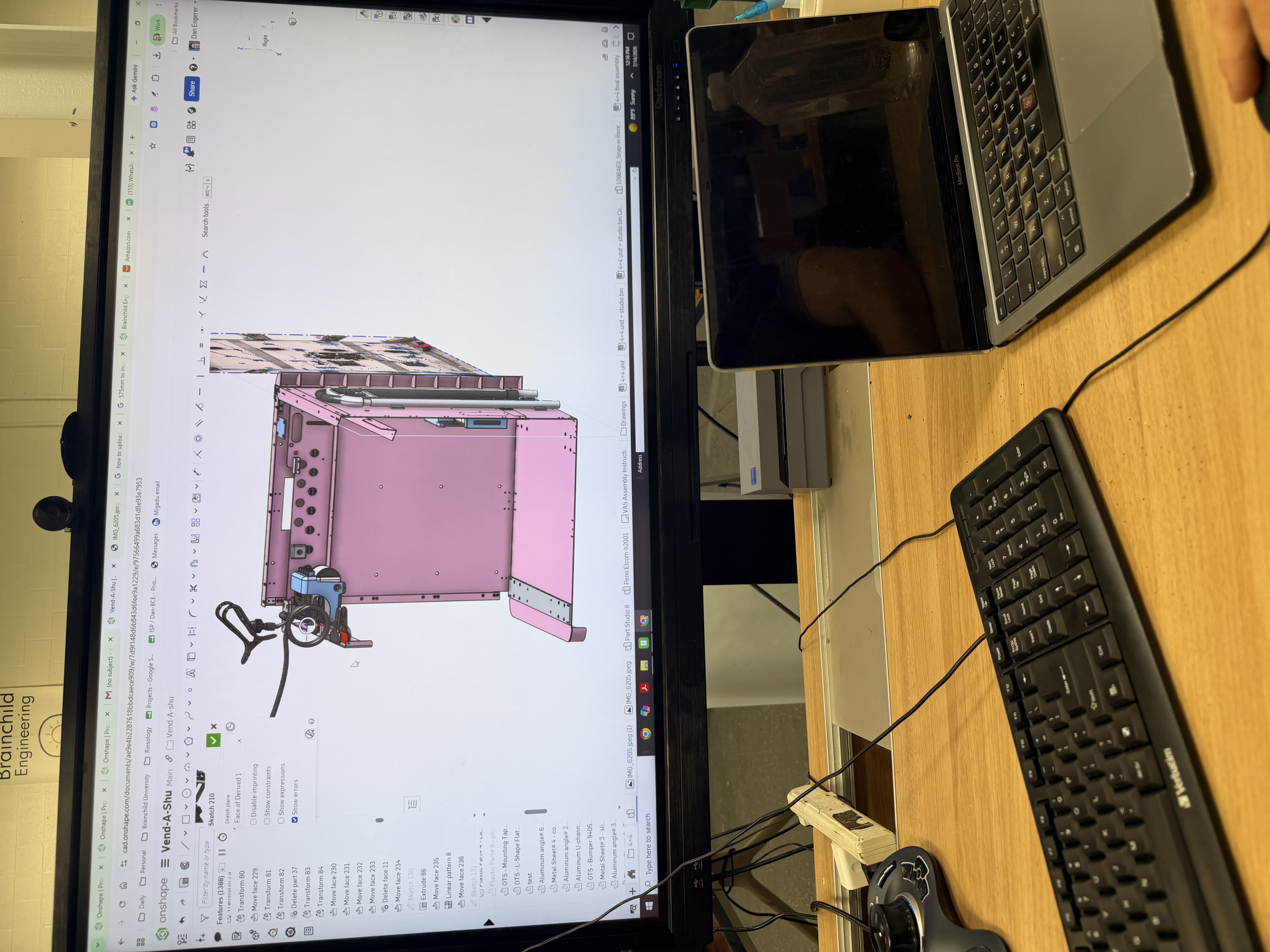
Full Vend-A-Shoe CAD assembly

Packaging built around servos, LEDs, fan, Pi, and harness; not a generic box.

Printed extenders
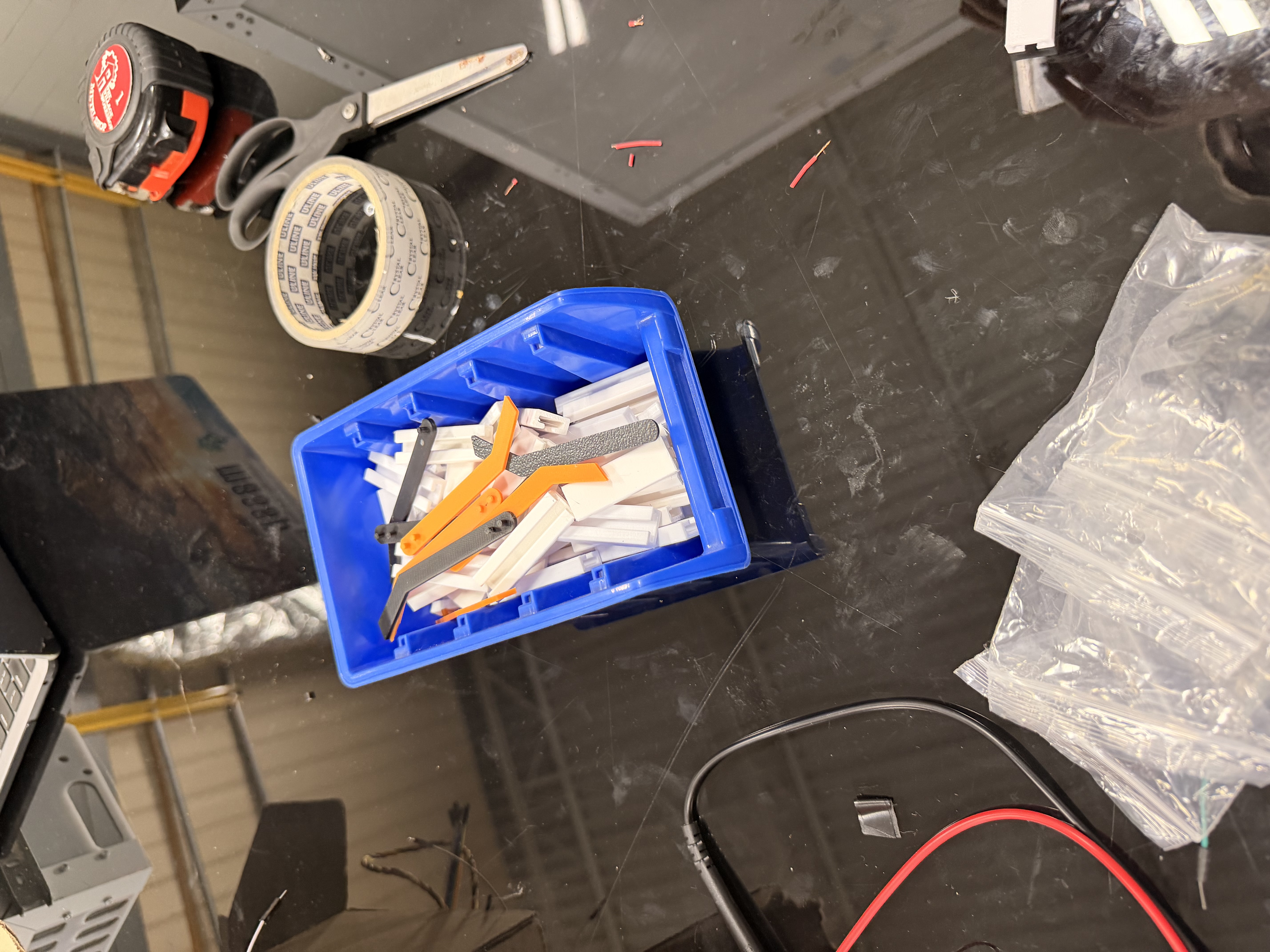
3D-printed mechanical extenders

Printed parts that made the dispense geometry and mounts fit the real box.
02Electrical

Electrical

Goal

Take a normal AC wall outlet, convert it to usable DC, and power the protoboard, 4 MG996R servos, 8 LEDs, the fan, and the Raspberry Pi from that one path without brownouts or sketchy grounds.

Design

Bench supply for bring-up; multimeter checks on rails and grounds before trusting a channel. Then a wall AC to DC / USB-C PD path into a soldered protoboard with common ground so the whole unit can leave the bench. This was one of the clearest electrical lessons from the internship: wall power is not just plugging something in; it is conversion, distribution, and load budgeting. Actuator and accessory current stay off the Pi GPIO path; GPIO only signals.

Challenges

  • We planned for four motors; a few were already fried and just sat dead. Later I connected the system to 24 V during a power mix-up and likely damaged more. Sorting wiring versus software versus dead hardware became its own debug loop.
  • Eight LEDs and a fan added continuous load on top of the servo harness; the wall converter and protoboard had to feed all of that plus the Pi.
  • Shared Pi power sagged under multi-servo moves; breadboard contacts lied; forty-plus wires made routing a design problem, not a cleanup task.
  • No experienced EE mentor, dull soldering iron, solder paste instead of proper wire, and no fume extraction. I was also teaching a teammate basic circuits while trying to bring the board up.

Iterations

  • Bench PSU for controlled bring-up; multimeter on voltage drop, continuity, and common ground before rewriting PWM code.
  • Swap-test motors and channels; watch LED and fan rails while servos move.
  • Soldered protoboard for permanence; wall AC to DC path so the packaged unit runs from a basic outlet.

Final implementation

One wall outlet path into DC distribution on the protoboard. That rail powers the motors, eight LEDs, the fan, and the Raspberry Pi in the shipped assembly.

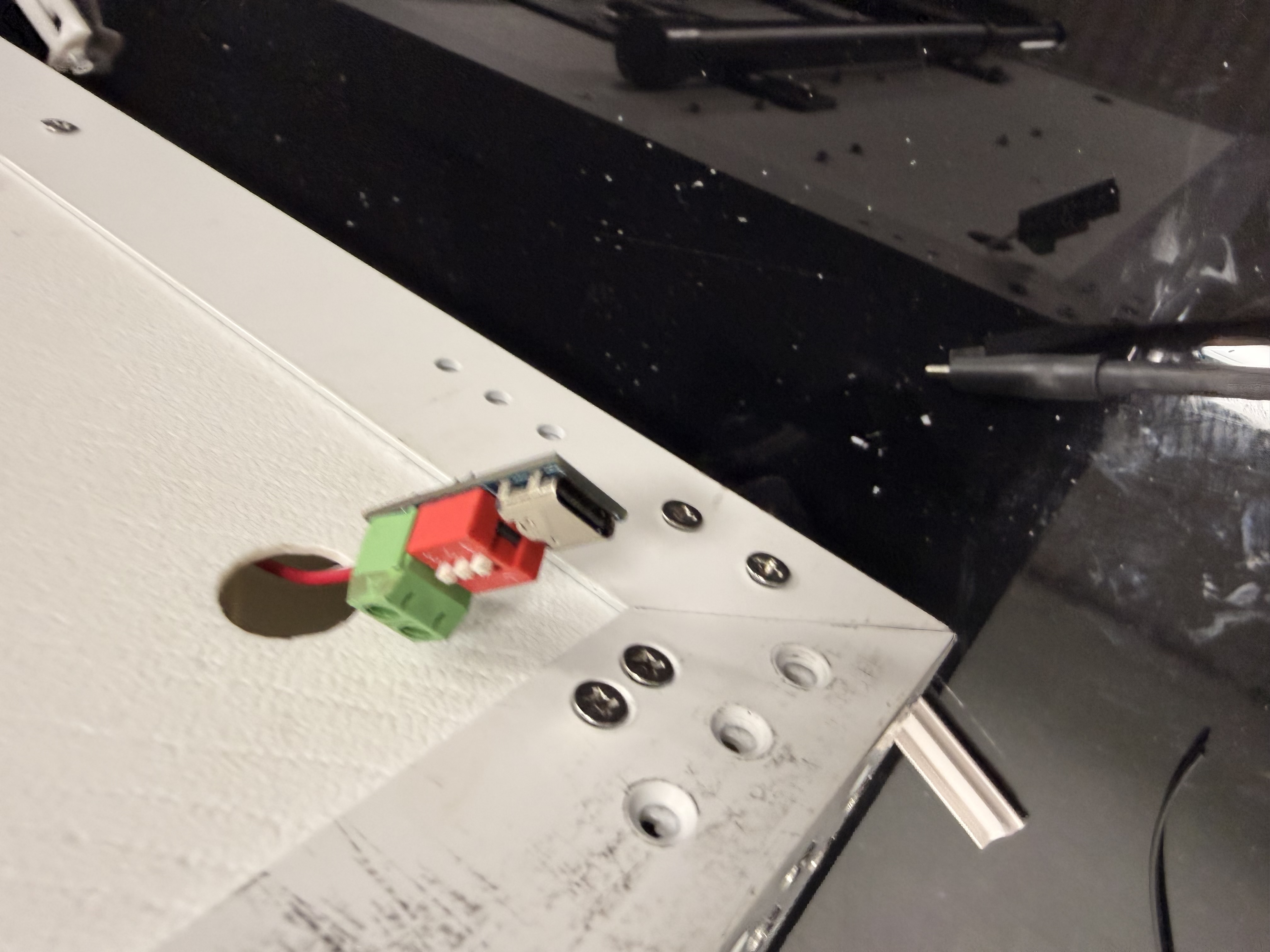
Wall AC to DC
Wall AC to DC power converter for Vend-A-Shoe

AC wall outlet into DC for the protoboard. Same path feeds the motors, 8 LEDs, fan, and Pi.

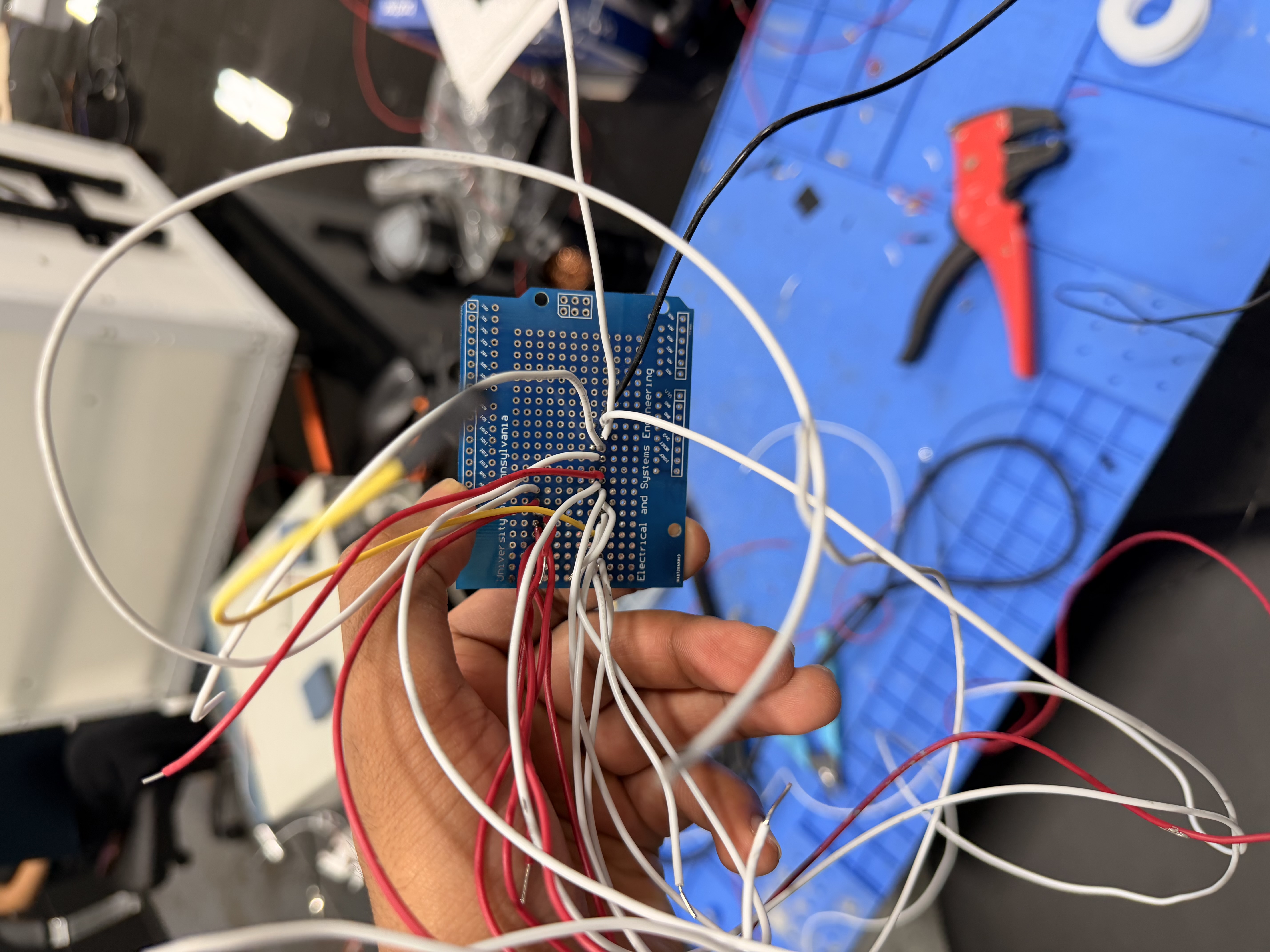
Protoboard front
Soldered protoboard front

Soldered permanence after the breadboard stopped being trustworthy.

03Embedded

Embedded

Goal

Turn a queued cloud command into one clean dispense motion and a status you can trust.

Design

Raspberry Pi 4; Python worker; RPi.GPIO PWM. Parses dispense_bin_n, applies per-bin target duty, returns home. systemd keeps the worker up across reboot.

Challenges

  • A silent motor looks identical to a bad pin map until you meter the rail, swap hardware, and prove which layer failed.
  • SSH disappeared after a Wi-Fi restart because DHCP handed out a new IP. It looked like a deeper OS failure until the address changed.
  • One shared motion profile over-rotated Bin 3.
  • Crashes mid-run left ambiguous state until running existed.

Iterations

  • Standalone scripts on the bench; channel swap tests before blaming software.
  • Polling worker with a single dispense action.
  • Four-bin map, duty overrides, systemd unit.

Final implementation

Claim-by-status worker with bin to GPIO mapping and calibration hooks. The unit wakes into a working loop without a laptop attached.

First working motor

Known-good channel proof before scaling to four lanes.

Pi motor bring-up

GPIO and PWM on the Pi once the channel and the motor were both known-good.

04Cloud & Integration

Cloud & Integration

Goal

Remote dispense without exposing the Pi, while keeping the frontend that already existed.

Design

Supabase queue as the boundary. New backend bent to the existing Next.js UI instead of rewriting the client.

Challenges

  • API shape had to match an independently built frontend.
  • Polling delay versus double-fire under concurrent claims.
  • Cross-stack failures only showed up end to end.

Iterations

  • Local-only GPIO scripts.
  • Cloud-connected single action.
  • Multi-bin queue plus UI status badges.

Final implementation

Browser click to durable row to physical dispense; completed and failed show up where you already look. The cloud path is software and queueing; wall AC to DC power lives in the electrical section.

Key Design Decisions

Calls I actually made

What else was on the table, what I picked, and why it still made sense once the hardware was real.

01

Raspberry Pi 4 over Arduino / ESP32

The problem

Need networking, a real OS, Python worker logic, and GPIO on one board.

Alternatives considered

  • Arduino plus a separate network module
  • ESP32
  • Raspberry Pi 4

Tradeoffs

MCU boards win on cost and boot time. Pi wins when the control path is a long-lived worker talking to Postgres.

Why I chose this

Pi 4. One platform for queue client, GPIO, and systemd; fewer failure domains during client demos.

02

Wall AC to DC into a shared protoboard rail

The problem

MG996Rs, eight LEDs, a fan, and the Pi need honest DC from a client-site wall outlet; a Pi USB cable cannot carry that load.

Alternatives considered

  • Power everything from the Pi
  • Separate supplies without a shared ground
  • Wall AC to DC into a common-ground protoboard

Tradeoffs

Pi-powered looks tidy until the first multi-servo move plus LED and fan load. Split grounds make GPIO references nasty. Wall conversion adds a part; it is what makes the unit shippable.

Why I chose this

Wall AC to DC feeding the protoboard, motors, LEDs, fan, and Pi together. Bench PSU and multimeter first; outlet path second. Internship takeaway: conversion and distribution are the product, not an afterthought.

03

Soldered protoboard instead of breadboard or PCB

The problem

Need reliability past Duponts without freezing a PCB while mounts were still moving.

Alternatives considered

  • Breadboard
  • Soldered protoboard
  • Custom KiCad PCB

Tradeoffs

Breadboard is fast and lies. PCB is right and slow when connectors still drift daily.

Why I chose this

Protoboard as temporary permanence. Next revision should be a PCB once connector positions stop moving.

04

Custom enclosure over a generic box

The problem

Off-the-shelf cases fight servo geometry and harness exits.

Alternatives considered

  • Generic project box
  • Custom Onshape enclosure plus printed mounts

Tradeoffs

Generic is faster day one. Custom costs CAD time; it buys serviceability.

Why I chose this

Custom box, printed mounts, laser-cut rear panel. Packaging was a design constraint, not a shell.

05

Adapt backend to existing frontend

The problem

UI already existed; backend and hardware were new.

Alternatives considered

  • Rewrite the frontend
  • Shape the backend to the existing app

Tradeoffs

Rewrite cleans the API. Adaptation keeps working UX and forces the interface to stay honest.

Why I chose this

Keep the frontend. Integration bugs beat a second UI rewrite on an internship clock.

When It Broke

Failures that looked the same until I measured

A quiet motor, a dead SSH session, and a bad joint all feel like “it just does not work.” The job was proving which layer actually failed.

Silent servos

What I saw
Motors sat quiet or barely twitched even when the wiring and code looked right.
What it actually was
Some motors were already damaged before I got them. Later, the 24 V mistake likely took out more. Bad contacts, weak supply current, wrong PWM, and dead hardware all look the same from the outside.
How I isolated it
Swap in a known-good motor, swap channels, meter the rail, change one variable at a time.
What I would do next time
Burn in every actuator before it hits the harness. Keep one golden motor and one golden channel.
Known-good proof

Substitution beat another full rebuild of a maybe-dead lane.

24 V on a low-voltage servo system

What I saw
Motors that had been working failed around the July 18–25 travel week after a bad power connection.
What it actually was
I connected the system to 24 V. An MG996R is not just a motor; it has a control board and driver electronics. Excess voltage can kill the electronics immediately and overheat the winding. At stall, current rises with voltage and heating rises with I²R.
How I isolated it
Own the mistake, stop guessing about firmware, replace the damaged units, and bring the system back up on a known rail with a meter.
What I would do next time
Keyed low-voltage connector, fuse or PTC per branch, reverse-polarity / overvoltage protection, labeled rails, and a short pre-power checklist before anyone energizes the harness.

SSH disappeared after Wi-Fi reset

What I saw
Could not SSH into the Pi after a network restart. It felt like the machine was dead.
What it actually was
DHCP gave it a new IP. SSH was fine; I was knocking on the old address. A borrowed monitor dependency made that take longer than it should have.
How I isolated it
Get a local display, read the new address, reconnect, then confirm how hostname access should work next time.
What I would do next time
Reserve a static DHCP lease, use mDNS / hostname, and document the fallback monitor path.

Fan branch that looked like a bigger failure

What I saw
Fan or a branch connection dropped out after soldering and packaging.
What it actually was
A bad solder joint, and separately a failed alligator clip, looked like a wider electrical problem until substitution narrowed it.
How I isolated it
Swap known-good wires, continuity-check the branch, reflow or replace the joint instead of rebuilding the whole board.
What I would do next time
Continuity-test each harness branch as it is finished. Temporary clips do not belong in the permanent path.
Fan + harness

Permanent fan branch after the joint and routing had to hold.

Evolution

How it got here

Bench bring-up, CAD fits, soldering, and the demos in between. Not just the final photo.

  1. Bring-up

    Breadboard, four motors, and a bad assumption

    We started with four motors on a floating harness. A few would not move at all; the unanticipated part was that they had already been cooked elsewhere. Wiring, software, and dead hardware all produce the same quiet servo. Proving which one it was became a microcosm of debugging across systems later.

    Initial breadboard wiring
    Initial breadboard wiring during bring-up

    Early architecture proof before anyone trusted a channel.

  2. Bench chaos

    Fan, LEDs, supply, and meter

    Eight LEDs and a cooling fan joined the servo load while the harness grew past forty wires. Bench power supply and multimeter work made sagging rails and bad grounds visible; without that, every flake looked like a software bug.

    Bench bring-up

    Fan in the loop; meter on the rail before rewriting code.

  3. First demo

    June 18–25 demo window

    fullvideoinitialdemo.mp4 sits here: early app-triggered path once a known-good motor and channel lined up, then more motors as replacements arrived. This window is demo progress, not travel.

    Full initial demo

    June 18–25 footage of the early end-to-end path.

  4. Permanence

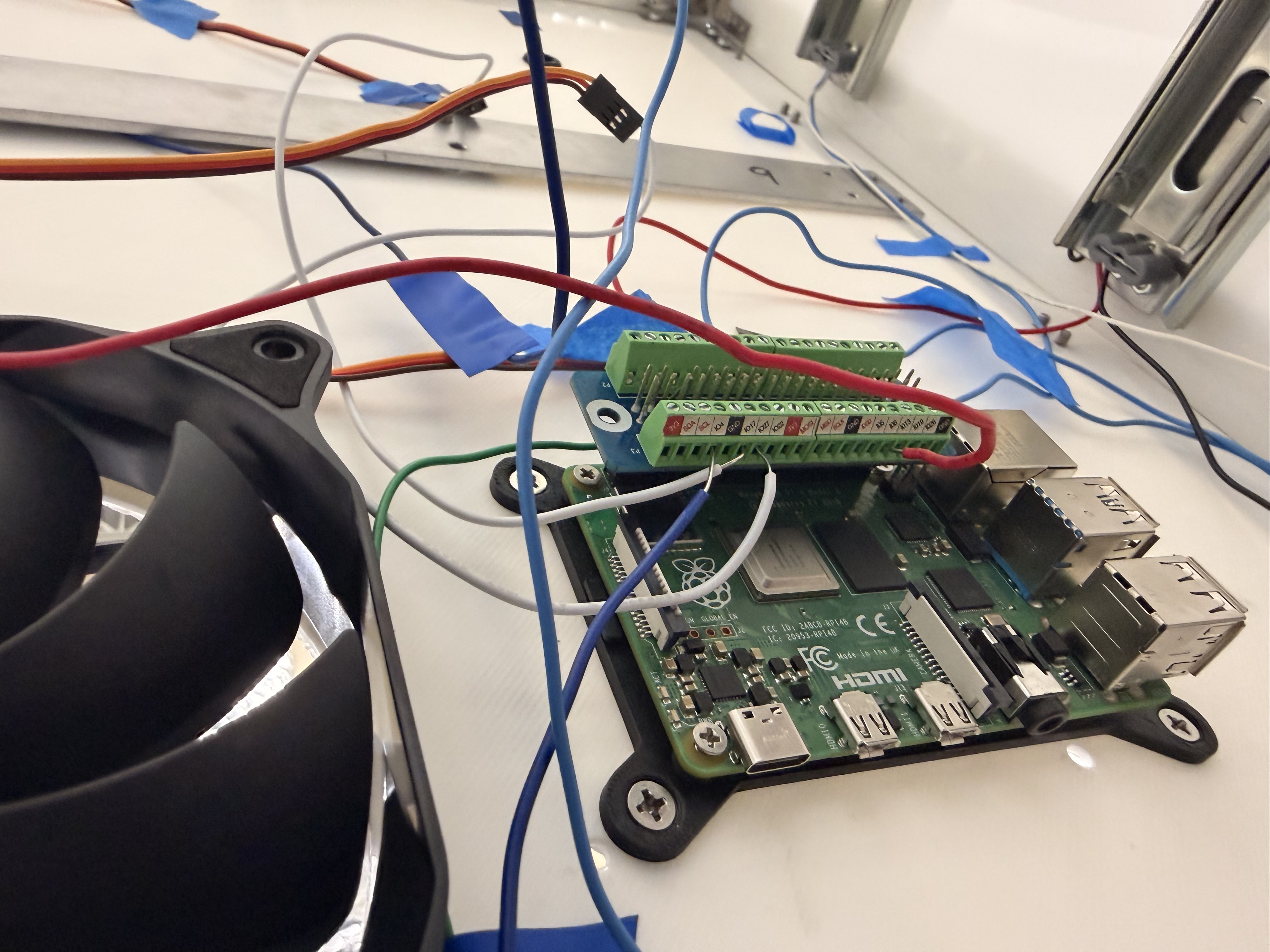
    Soldered protoboard and screw terminals

    Moved signal and power for servos, LEDs, and fan onto soldered joints and Pi screw terminals so the harness survived transport and demos.

    Protoboard build

    Breadboard habits do not survive a dense harness and a client handoff.

  5. Packaging

    CAD enclosure and printed mounts

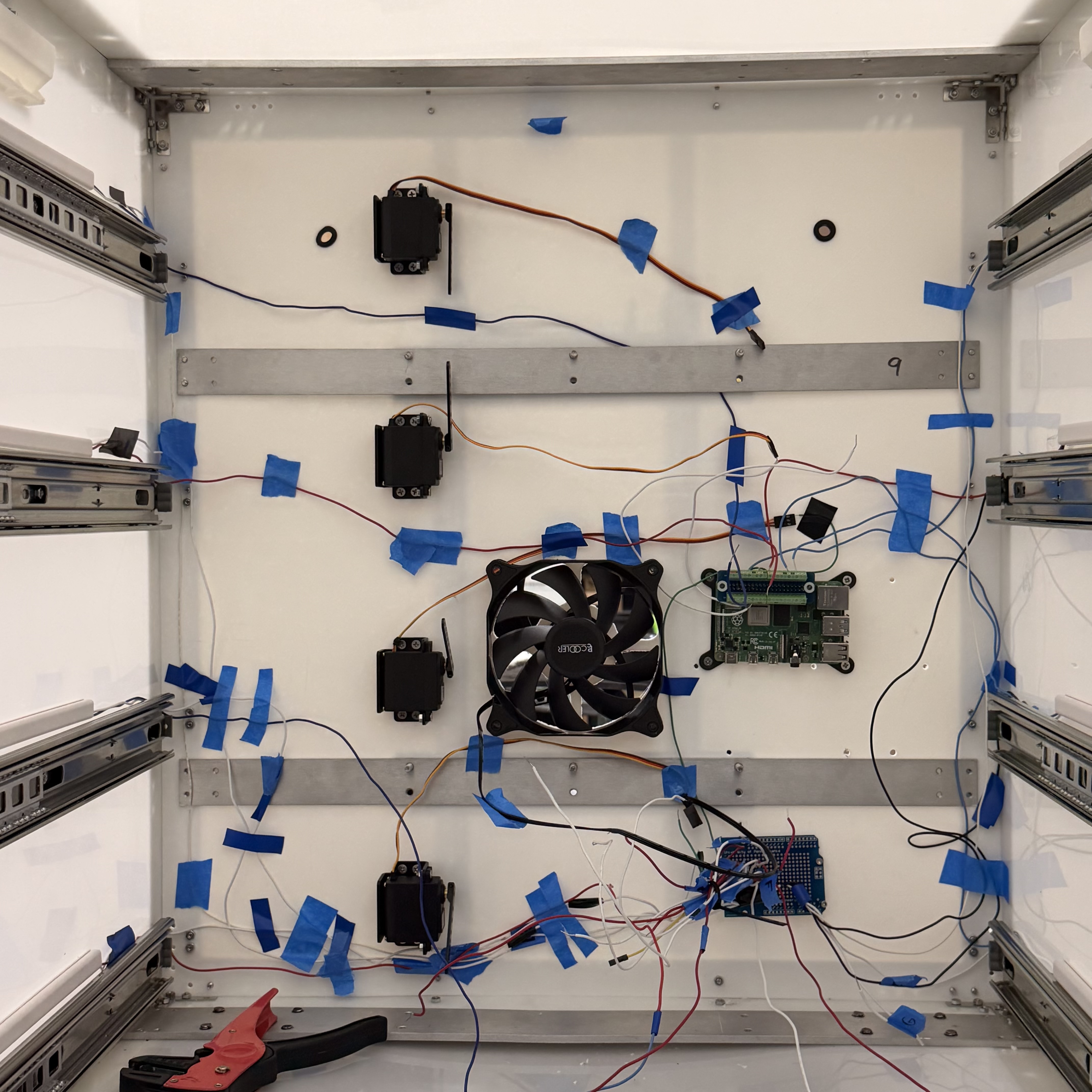
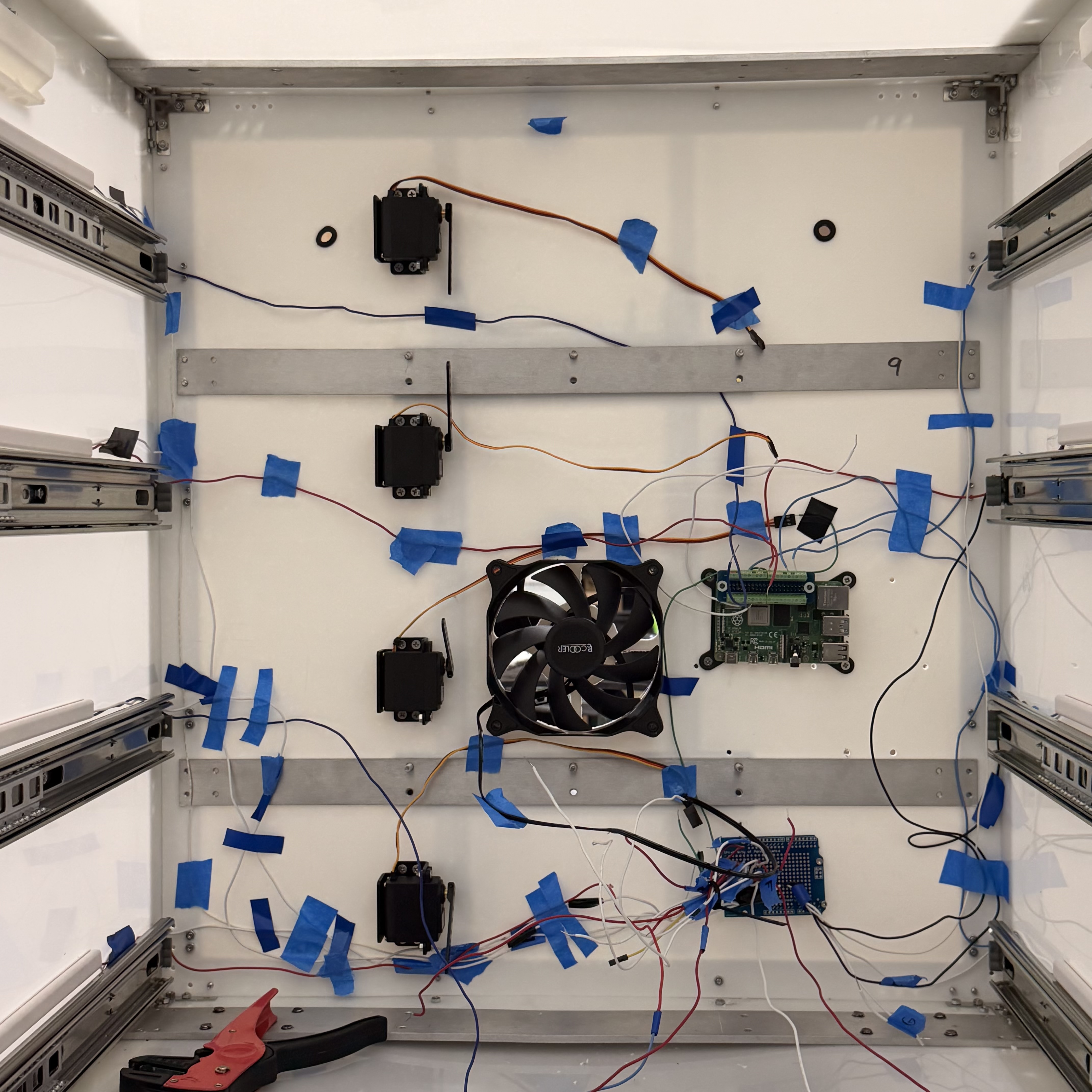
    Enclosure revisions tracked real clearances once harness lengths for motors, eight LEDs, and the fan were known; mounts, covers, rear panel. Bundling and wire covers were part of making the unit shippable.

    Bundled harness

    Routing became a designed subsystem once lengths were committed.

  6. Ship

    Wall power and end-to-end dispense

    After the July 18–25 travel week and motor replacements, wall AC to DC cut the bench supply once the meter said the rails were honest. LED color mismatch got corrected. Multi-bin calibration and UI status closed the loop for delivery.

    Dispense demo

    Queued command to physical dispense on the assembled unit.

What Took Time

Where the calendar went

Calendar time was dominated by harness, power permanence, and recovery—not by writing the queue worker.

Had to happen

  • Qualify every servo/LED/fan before trusting the software map
  • Bench-supply bring-up with current limit before wall power
  • Protoboard + labeled harness once the connector map froze
  • Packaging that still opens for service after transport

I could have prevented

  • Cutting wire lengths before the mounting layout was frozen
  • Assuming quiet motors meant bad code instead of swap-testing first
  • The 24 V overvoltage connection—and the recovery cost that followed
  • Leaving final multi-bin validation until the delivery week

Environment around me

  • No EE mentor on-site for early power review
  • Protoboard and decent soldering tools not in stock at first
  • Travel week coincided with a power fault while I was away
  • Limited spare-qualified actuators when motors failed

Version 2

How I would build the next one

If I built the next unit with what I know now, I would aim for roughly 3–4 calendar weeks of part-time work instead of rediscovering the same failure modes. That only works if parts are available and the connector map freezes early.

  1. 1

    Freeze the requirements

    Actuator count, LED behavior, fan, wall input, connector locations, service access, software interface, acceptance tests. One-page diagram and a power budget before cutting wire.

  2. 2

    Qualify every actuator first

    Bench-test every servo, LED pair, fan, and converter. Label PASS/FAIL. Keep one golden channel.

  3. 3

    Prove one complete lane

    Protected bench supply with current limit. One servo + LED + queue + status write-back for dozens of cycles before scaling to four bins.

  4. 4

    Freeze power, then build the board

    Rails, fusing, ground, connectors, gauges. Power review before energizing everything. Prefer a KiCad distribution PCB once the map is stable.

  5. 5

    Harness, package, validate

    Cut list, labels both ends, continuity as you go, then mounts and covers. Written test matrix: each bin, reboot, Wi-Fi reconnect, tug test, thermal check.

Design changes I would make

Power

Regulated low-voltage supply sized for stall current; fuse/PTC per branch; reverse-polarity and overvoltage protection.

One bad connection should not kill every actuator.

PCB

Custom KiCad distribution board with keyed connectors, test points, and clear silk.

Less hand soldering, fewer polarity mistakes, faster assembly.

Networking

Static DHCP reservation and mDNS hostname.

SSH does not disappear every time Wi-Fi resets.

Sensing

Optical, load, or limit sensing on the dispense path.

“Servo moved” stops pretending to mean “shoe dispensed.”

Build docs

Harness drawing, cut list, and a simple test traveler.

Someone else can build and check the next unit.

Results & Validation

What held up

What worked in the end, what I can show for it, and where it's still limited.

Client delivery

Shipped

Assembled unit left as a working product; enclosure, dense harness, power, and cloud-triggered dispense included.

Multi-bin actuation

Calibrated lanes

Each bin maps to its own GPIO path and motion profile; Bin 3 uses a reduced target duty after over-travel showed up in testing. Dead motors got swap-tested out before we trusted the map.

Wall-powered stability

Wall AC to DC

Wall AC to DC into a common-ground protoboard carried servos, eight LEDs, the fan, and the Pi without brownouts after bench PSU and multimeter bring-up.

Remote command path

Queue loop

Dashboard enqueue; worker claim; status write-back. The Pi stays off the public internet.

Photos and clips

The runs and stills that match the results above.

Working model

Assembled system running the full dispense path.

Validation demo

End-to-end dispense on the packaged unit.

LED mismatch catch
Finalized assembly where LED color mismatch was caught

Late mismatch corrected before handoff, not ignored.

Assembled unit
Assembled Vend-A-Shoe

Final mechanical and electrical packaging.

Enclosure cover
Enclosure CAD cover view

CAD that matches what shipped.

Stage 1 assembly
Early Vend-A-Shoe assembly stage

Mid-build packaging before the harness settled.

Early still
Early Vend-A-Shoe bring-up still

Bench state before permanence.

Pi in place
Raspberry Pi in the assembly

Screw-terminal harness into the Pi; reworkable, not a Dupont nest.

Limitations

  • No sensor confirmation of a successful drop; motion complete is not the same as item dispensed.
  • Protoboard wiring will not scale cleanly past this unit count.
  • Queue auth is still MVP-grade for a public multi-user deployment.
  • Not production-ready: no formal safety certification or high-volume validation.

What This Built

Habits I want to keep carrying

Not a résumé keyword list. These are the instincts this build forced.

Low-voltage systems

Brought actuators up on a bench supply, then moved to wall-powered distribution with a shared ground, load budgeting, and a harness that had to survive transport.

Useful anywhere a small mistake on a rail can take out a whole actuator set.

Dense packaging

Co-designed enclosure clearances, connector placement, wire covers, and service access so the final box was not just closed, but openable again.

Useful when the CAD model and the harness disagree and both still have to ship.

Cross-layer debugging

Silent motors, DHCP/SSH loss, bad joints, and cloud queue bugs all presented as “it does not work” until meters, substitution, and status transitions isolated the layer.

Useful when hardware, firmware, and networking fail with the same external symptom.

Verification mindset

Commanded motion is not verified delivery. I would add sensing and a written acceptance matrix before calling the next unit done.

Useful when the cost of a false “success” is higher than the cost of another sensor.

Reflection

Looking back

What surprised me, what I'd redo, and questions I'm still chewing on.

What surprised me

  • The biggest lesson was how to debug across numerous systems at once. Mechanical, electrical, embedded, and cloud failures share symptoms; the work is picking a layer, measuring it, and only then moving.
  • Some of the four motors were already fried; the quiet failure looked like bad wiring or bad code until a swap test and a meter reading forced the assumption to break.
  • I also made a real power mistake: connecting the system to 24 V. I own that. The slow recovery around it also showed how little protection, review, and spare qualification existed in the environment.
  • Eight LEDs, a fan, and forty-plus wires ate more calendar than the PWM math; harness planning was the real schedule risk.
  • Bench power supply and multimeter work caught sag and ground issues that software logs never would have named correctly.
  • Breadboard success did not transfer; permanence changed the failure modes.

What I would redesign

  • KiCad PCB with keyed servo, LED, and fan connectors plus onboard regulation and branch protection.
  • Closed-loop dispense sensing with an optical or limit switch.
  • Standardized connectors so a failed servo is a module swap, not a re-solder.
  • Incoming actuator burn-in so dead hardware does not masquerade as a software bug.
  • Static DHCP reservation / mDNS so SSH does not vanish after every Wi-Fi reset.
  • Harness drawing and cut list before the first wire length gets committed.

Future improvements

  • Build the next unit on the Version 2 sequence instead of rediscovering the same blockers.
  • Injection-aware enclosure consolidation once the connector map freezes.
  • OTA updates and basic device health.
  • DFM pass once packaging stops moving daily.

Questions that emerged

  • When does protoboard stop being honesty and start being technical debt?
  • How should power topology change when every unit also carries LEDs, fans, and dozens of harness branches?
  • What does maintainability look like when the first owner is not the builder?