← Back to Projects
EmbeddedShippedFeatured

Automatic Tennis Ball Shooter

Designed and fabricated a client tennis-ball launcher prototype at BrainChild Engineering integrating ESP32 wireless control, dual RS-775 flywheel drive, NEMA 17 stepper feed, MOSFET motor switching, and 12V-to-5V power regulation into a modular electromechanical system.

I built this at BrainChild Engineering for a client demo that had to leave USB babysitting. The work meant migrating from an Arduino Mega / Bluetooth path to an ESP32 that owned motor sequencing; driving dual RS-775 flywheels through MOSFET modules under MCU PWM instead of pot speed controllers; indexing balls with a NEMA 17 on an A4988; and splitting a fused 12 V pack so actuators stayed on the high rail while a buck fed 5 V logic. The MOSFETs are hard switches: PWM duty cycle sets average motor voltage, and the motor’s inductance / inertia smooth the pulses. Failures taught as much as the architecture: no buck at first left the ESP32 dead on battery, the stepper print was too flimsy until a denser reprint, and a PWM test oversped a motor so hard that the fuse did not open, buck / battery solder joints came off, and a wire melted. It stayed a prototype on purpose: enough for a Replit-controlled multi-motor demo, not a finished consumer launcher.

Engineering highlights

  • Drove flywheels with MOSFET modules under ESP32 PWM so speed is duty cycle, not a half-on FET dumping heat
  • Split a fused 12 V pack: actuators on the high rail, bucked 5 V for ESP32 / driver logic
  • Survived an overspeed event where the fuse missed, buck/battery joints failed, and a wire melted, then hardened the bring-up checklist around protection and joints
Date
2025–2026
Focus
Electromechanical Systems
Build stage
Client prototype / demo
Disciplines
Embedded Systems · Electrical Engineering · Mechanical Design · Power Electronics · Robotics
ESP32BrainChildMOSFETPWMBuck ConverterFuse3D PrintingRobotics
App demo

BrainChild client demo path: Replit UI into the ESP32 launcher stack.

Full write-up below. The hero is the short version. This is the build story: what I designed, what broke, and why I made the calls I did.

Motivation

Why I started this

What pulled me in, and what I wanted to get better at.

Why I built it

This was a client build at BrainChild Engineering. The brief was an automatic tennis ball launcher the team could demo from a phone, not a one-off bench trick that only worked with USB power and babysitting.

What interested me

The interesting part was not “make a ball fly.” It was getting wireless control, motor sequencing, a fused 12 V actuator rail, a bucked 5 V logic rail, and a mechanical feed to behave like one machine under client demo pressure.

What I wanted to learn

Coursework had given me programming and basic electronics separately. This was practice when voltage domains, print strength, PWM switching, and app timing fail with the same external symptom until you isolate a layer.

System Overview

How the system fits together

A Replit web app talks to an ESP32. Firmware turns those commands into motor sequencing through breadboard interface circuitry: MOSFET modules that PWM-switch the flywheel motors, an A4988-class stepper driver for the feed, a fused 12 V battery rail for the loads, and a buck converter that steps that rail down to 5 V for the ESP32. Two RS-775 DC motors spin printed flywheels; a NEMA 17 stepper indexes balls into the launch path.

01

Web / wireless control

Replit control UI sends commands; ESP32 owns sequencing / timing in firmware.

02

Power architecture

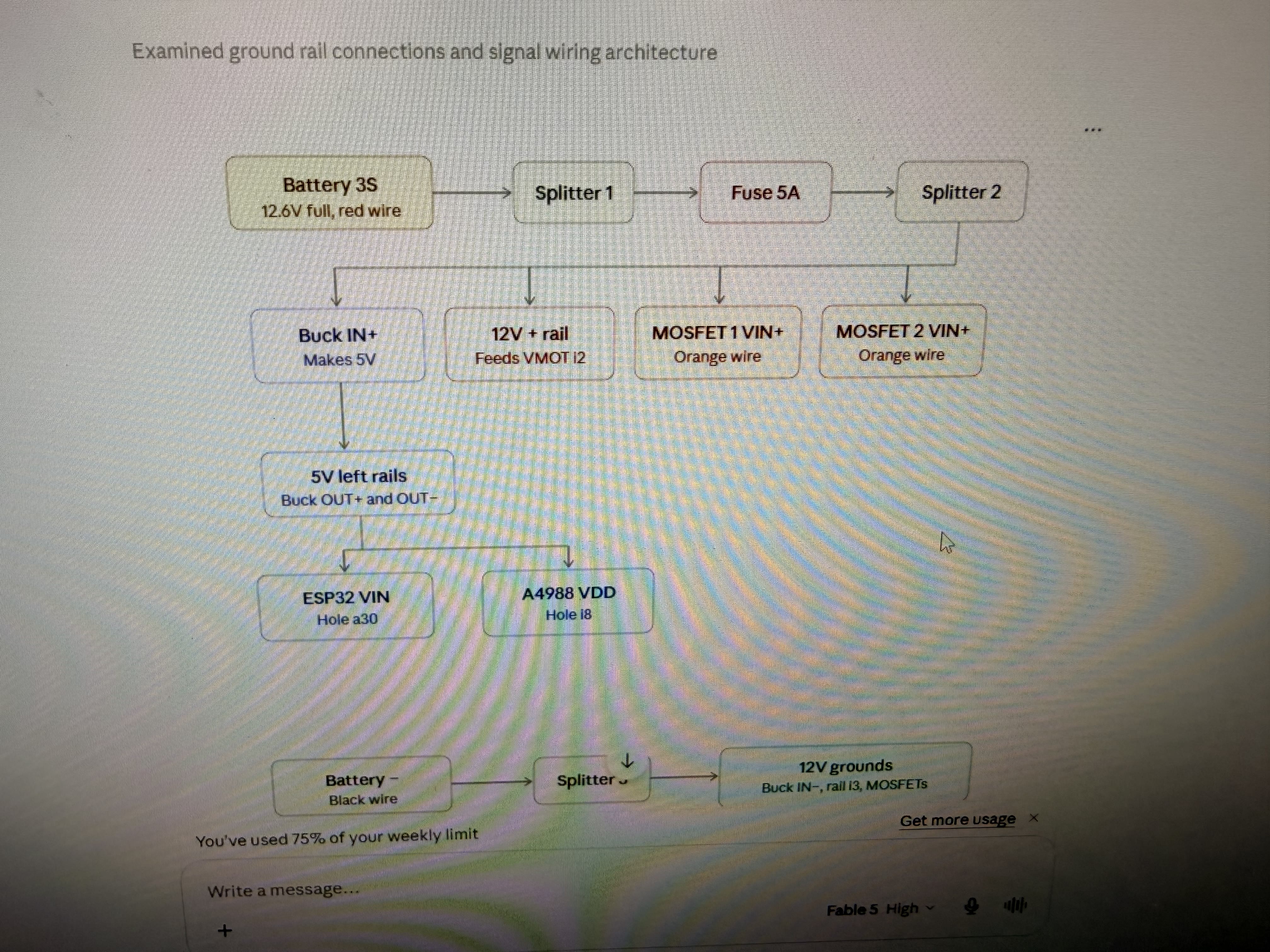
12 V battery → fuse → splitters → MOSFET VIN + stepper VMOT; buck → 5 V for ESP32 / A4988 logic. Fuse is there to open the pack path if current goes wrong.

03

MOSFET PWM drive

MCU PWM into MOSFET gates; modules act as fast switches, not linear resistors, so flywheel speed is duty cycle, not a half-on MOSFET burning heat.

04

Ball feed

NEMA 17 stepper-driven indexing on a printed coupler / mount that had to survive torque.

05

Launcher drive

Dual RS-775 DC motors on printed flywheels; PWM duty sets release speed.

06

Chassis & mounts

Panel enclosure with printed brackets so actuators can move during iteration.

Data flow

Replit UI → ESP32 → GPIO / PWM / STEP·DIR → MOSFET modules + A4988 → RS-775s + NEMA 17 → feed + launch.

Control flow

Firmware owns motor timing and release behavior. The app sends commands; it does not drive actuators directly. Logic never shares the raw 12 V rail. The fuse sits on the pack path as the last hard stop if current spikes.

Power architecture
Power and signal wiring diagram with 12V battery, fuse, MOSFETs, and buck to 5V

3S battery through a fuse and splitters to MOSFET VIN and stepper VMOT. Buck IN+ takes the same high rail and makes 5 V for ESP32 VIN and A4988 VDD. The fuse is meant to open the pack connection if current runs away.

Engineering Breakdown

Broken down by discipline

Each block covers the goal, the design, what broke, what changed, and what shipped.

01Mechanical

Mechanical

Goal

Hold two flywheel motors and a stepper feed in a layout that could change without reprinting the whole machine, and keep printed interfaces stiff enough under real torque.

Design

Panel chassis with printed corner braces and motor mounts. Two RS-775s on L-brackets; NEMA 17 on a center printed stack for indexing. Early coupler / mount prints were too flimsy under stepper load.

Challenges

  • The first 3D-printed part on the stepper was under-infilled and poorly fastened. It flexed and would not hold under torque.
  • Clearances only became real once both RS-775s and the stepper occupied the same volume.

Iterations

  • Low-infill coupler / mount that looked fine on the bench and failed under load.
  • Reprint in Bambu Studio (PETG, Strength tab) with higher infill density so the part was heavier and stiffer.
  • Re-fastened the stepper interface once the printed geometry could take the load path.

Final implementation

A modular mechanical stack good enough for prototype integration once the stepper print stopped being the weak link.

Print failure

First printed interface on the stepper: too flimsy and not fastened well enough. Flex under torque made the feed look like a firmware bug until we blamed the plastic.
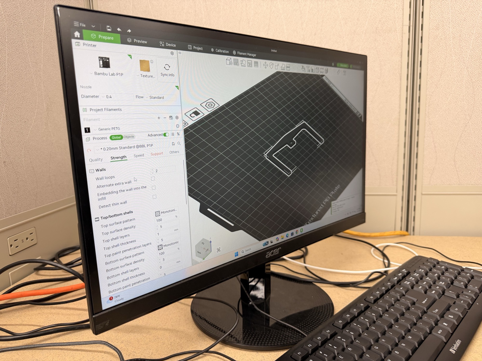
Higher-infill reprint
Bambu Studio Strength settings for reprinting the stepper mount

Bambu Lab P1P / PETG prepare view with the Strength tab open. Reprinted the U-bracket / mount denser so it could take stepper torque without folding.
02Electrical

Electrical

Goal

Run high-current flywheels and a stepper off a 12 V pack without killing a 5 V ESP32, switch motors efficiently with PWM, and keep a fuse in the pack path for overcurrent.

Design

Fused 12 V battery rail for MOSFET modules and stepper VMOT. Buck converter steps that rail to 5 V for ESP32 and driver logic. The MOSFETs are not “variable resistors.” The ESP32 drives their gates with PWM so each device hard-switches between nearly full pack voltage and off. Duty cycle sets average motor voltage; motor inductance and inertia smooth the pulses. That is why a half-speed command does not dump tens of watts into a half-on FET.

Challenges

  • Early bring-up had no buck converter. The pack was 12 V; the ESP32 wants ~5 V. Without the step-down, the control side would not run correctly off battery.
  • During MOSFET PWM testing the motor oversped hard, as if it were seeing a continuous 12 V rail. The fuse did not open the way we expected.
  • Solder joints on the buck converter and battery path came off under that event. With the joint gone, current had nowhere honest to go and a wire melted / charred.

Iterations

  • Battery toward the logic side without regulation: dead end.
  • Added a buck module so ESP32 VIN and A4988 VDD sat on a real 5 V rail, with a fuse on the pack feed.
  • MOSFET PWM modules for flywheel duty; then a forensic pass after the overspeed / melted-wire failure.

Final implementation

Prototype interface: fused 12 V rail for actuators, bucked 5 V for logic, MOSFET PWM for flywheels, A4988 for the NEMA 17. Fuse and joints became as much of the design as the modules themselves.

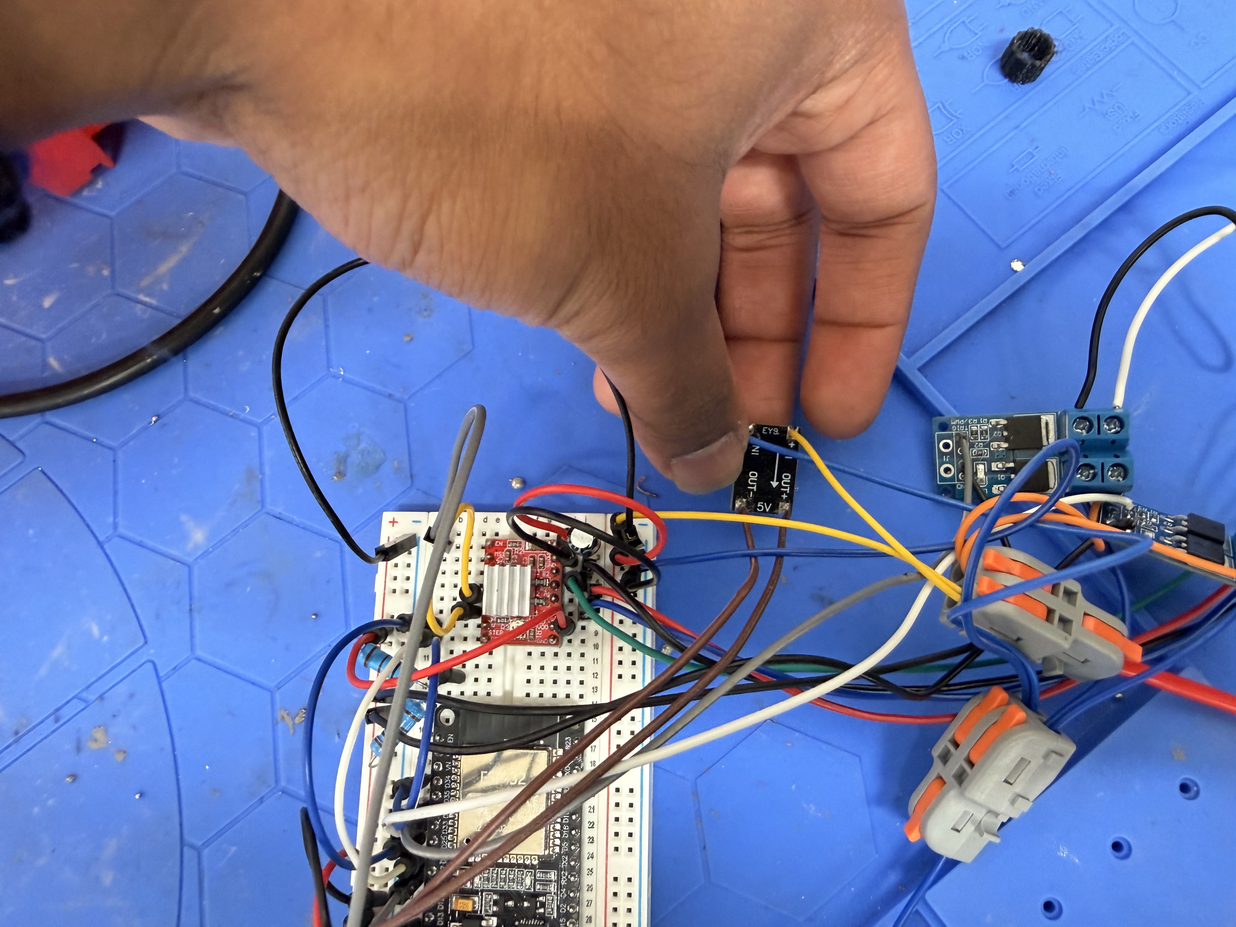
12 V → 5 V buck
Buck converter module held above ESP32 breadboard

Buck board labeled IN-/OUT-/IN+/OUT+/5V above the ESP32 breadboard and red A4988. Logic lives here; motors stay on the fused high rail.

MOSFET PWM switch

Blue dual-MOSFET module: MCU PWM into the gate / SIG path, screw terminals on the motor rail. Hard on/off switching at PWM rate, not a linear 6 V drop across the FET.

03Embedded

Embedded

Goal

Coordinate web-app commands, stepper indexing pulses, and flywheel PWM on one controller the client could demo.

Design

Started on an Elegoo Mega 2560 with Bluetooth-side phone control. Migrated to ESP32 so wireless and motor timing lived on one board. A Replit web UI (feed pace, rest interval, emergency stop, live rail readout) sends commands; firmware owns STEP/DIR to the A4988 and PWM into the MOSFET TRIG pins.

Challenges

  • Arduino + Bluetooth was fine in controlled tests and unreliable for consistent app-level control.
  • Multi-motor timing only makes sense once the power path and mounts are stable enough to trust.
  • App / firmware / hardware faults presented as the same “it doesn’t shoot” until we isolated a layer.

Iterations

  • Mega 2560 + Bluetooth path for phone control.
  • Migration to ESP32 for integrated wireless.
  • Replit control UI: START FEED, pace presets, rest between shots, emergency stop, live voltage.

Final implementation

ESP32 as the control brain: web commands in, sequenced STEP/DIR + PWM out through the interface circuitry.

Replit control UI

Web app on Replit: LIVE rail readout, REST BETWEEN, FAST/MED/SLOW pace, START FEED, and emergency stop. This is the client-facing command surface into the ESP32.

Key Design Decisions

Calls I actually made

What else was on the table, what I picked, and why it still made sense once the hardware was real.

01

ESP32 over Arduino Bluetooth

The problem

Phone / web control needed to stay reliable for a client demo while the machine was still changing.

Alternatives considered

  • Arduino Mega + Bluetooth module
  • ESP32 with integrated wireless

Tradeoffs

The Mega path was familiar and already partly wired. ESP32 meant a redesign, but the communication path stopped being the main failure mode.

Why I chose this

Migrate to ESP32. Changing the architecture beat endlessly patching an unsuitable link.

02

PWM-switched MOSFETs instead of linear drive

The problem

Flywheel speed had to be a firmware parameter without cooking the switch.

Alternatives considered

  • Pot speed controllers
  • Hold the MOSFET “halfway on” like a resistor
  • Hard-switch with PWM duty cycle

Tradeoffs

A half-on FET at several amps burns power as heat. PWM keeps the FET near fully on or fully off so dissipation stays low while average motor voltage tracks duty cycle.

Why I chose this

ESP32 PWM into MOSFET gates on the 12 V motor path. Duty cycle commands speed; the motor’s inductance and inertia do the averaging.

03

Series fuse on the 12 V pack rail

The problem

A short or runaway motor current needs a hard interrupt, not hope.

Alternatives considered

  • No protection
  • Software current limit only
  • Inline fuse on the battery feed

Tradeoffs

A fuse is slow and blunt, and ours did not save us during the overspeed event. Skipping it is worse. Software limits still need a physical backstop.

Why I chose this

Keep the fuse in the pack path. After the melt, treat fuse rating, joint quality, and PWM fault modes as one failure chain.

04

Buck converter between 12 V pack and ESP32

The problem

The battery was a 12 V-class pack; the ESP32 logic rail is 5 V.

Alternatives considered

  • Feed the MCU somehow off the pack without regulation
  • Step down with a buck module

Tradeoffs

Skipping the buck looks simpler until nothing boots. A buck adds one more module and wiring, but it is the difference between a demo and a dead board.

Why I chose this

Fused 12 V for motors; bucked 5 V for ESP32 and driver logic.

05

Higher-infill reprint for the stepper interface

The problem

The printed part on the stepper flexed and would not stay fastened under torque.

Alternatives considered

  • Glue / tape the weak print
  • Reprint denser and re-fasten

Tradeoffs

A denser print is heavier and slower. A light print is fast until the feed path is a joke.

Why I chose this

Reprint with higher infill density and treat fastening as part of the mechanical design.

Evolution

How it got here

Bench bring-up, CAD fits, soldering, and the demos in between. Not just the final photo.

  1. Electronics

    Mega, pot controllers, and a stepper driver

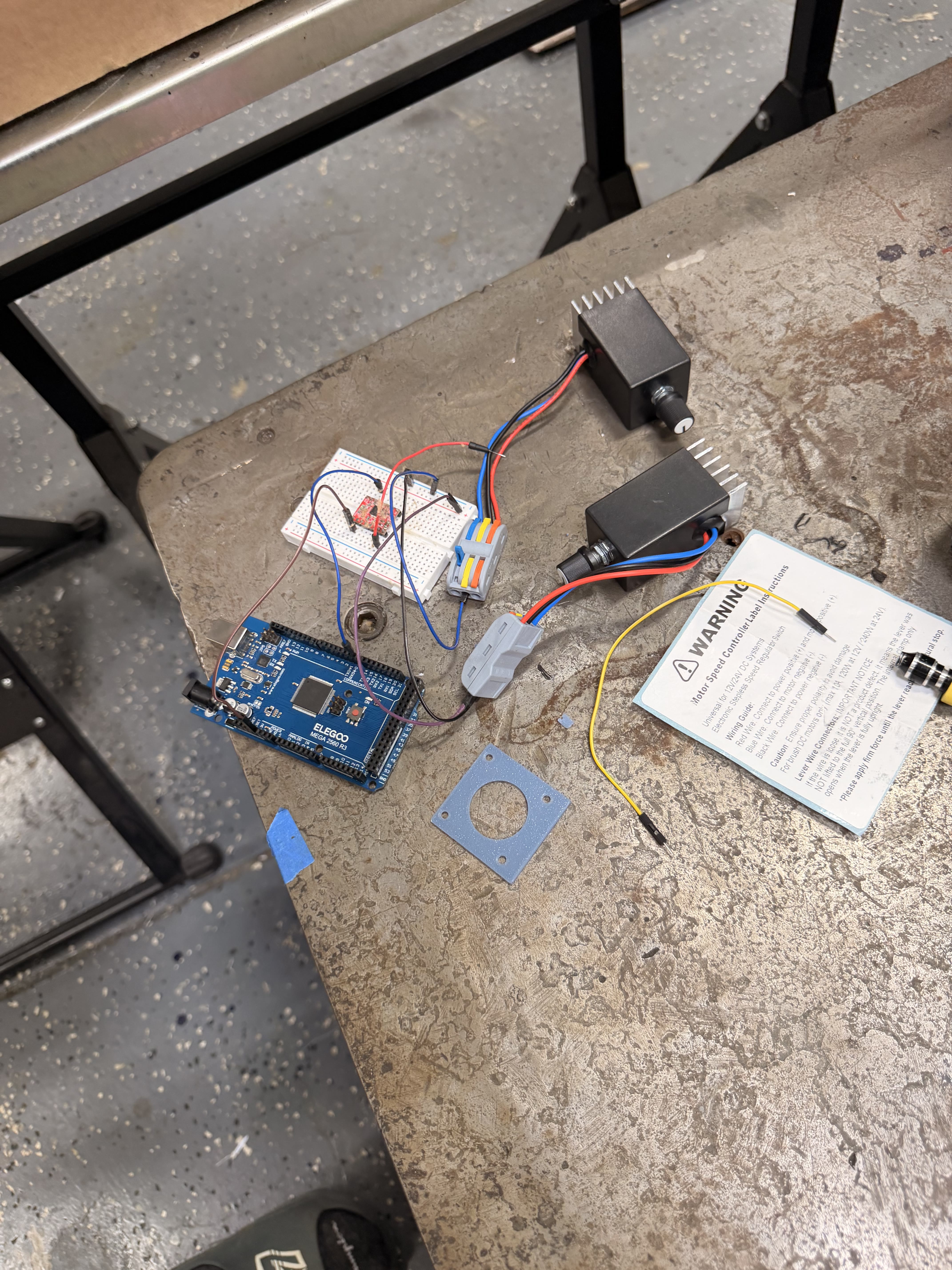
    First bench stack: Elegoo Mega 2560 for logic, two heatsinked DC speed controllers for the flywheels, and a red A4988-class driver for the feed. Flywheel RPM was still a manual pot.

    V0 electrical stack
    Elegoo Mega 2560 with two DC speed controllers and a red stepper driver

    Blue Mega 2560 at left. Two black pot-and-heatsink DC speed controllers for the RS-775 rails. Red stepper driver on the mini breadboard. Wagos as the power split.

  2. Power

    Buck, fuse, and a real 5 V logic rail

    Battery bring-up failed without regulation. The architecture became: pack → fuse → high-current splits for MOSFETs / VMOT, and a buck branch for ESP32 + driver logic.

    Control + power hub
    ESP32 breadboard with fused DC rail and Wago power distribution

    ESP32 on the breadboard after the power architecture settled: fused high-current bus, Wagos, jumpers out to MOSFET PWM and the stepper driver.

  3. Failure

    Overspeed, fuse miss, melted wire

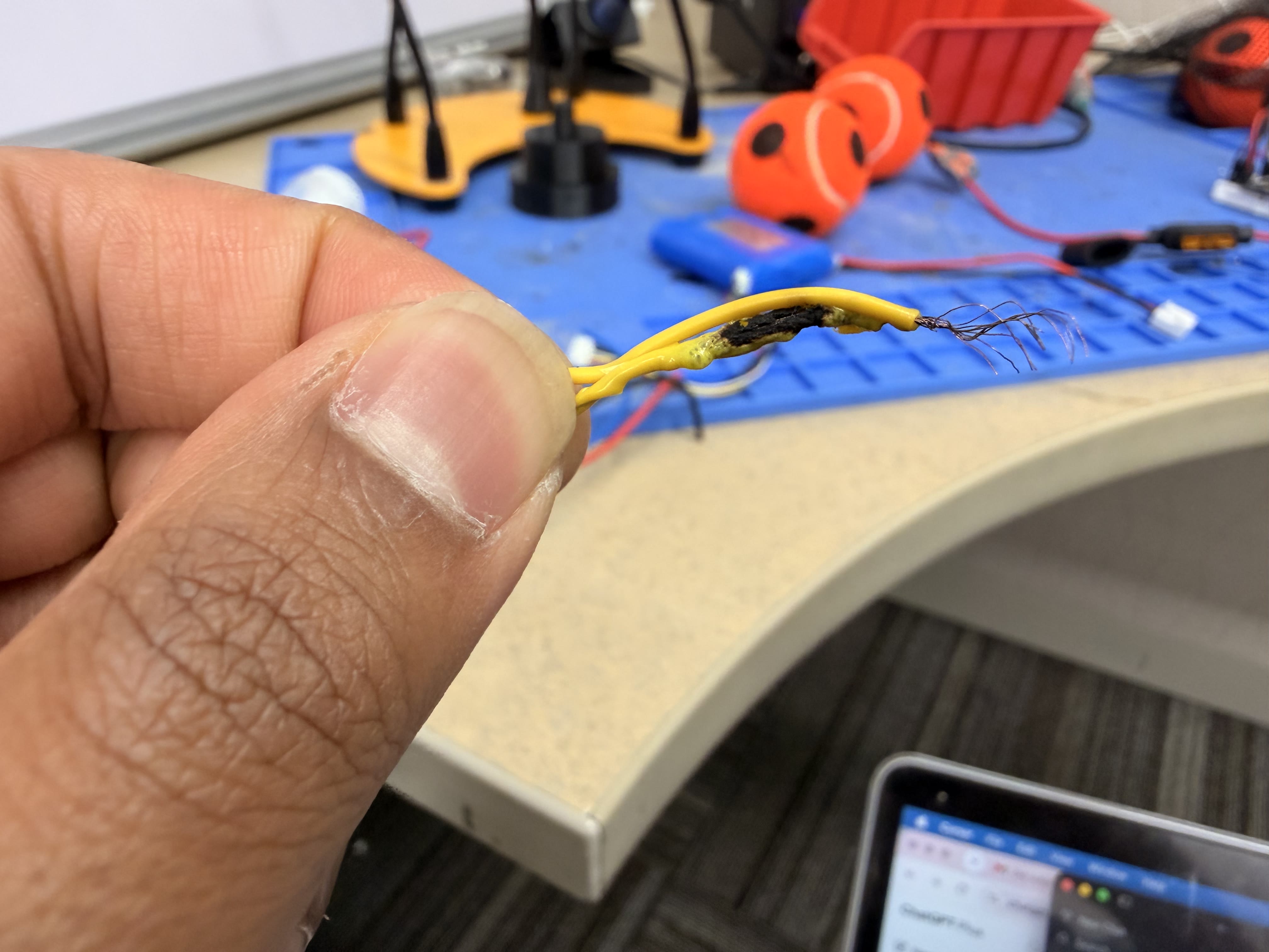
    While testing MOSFET PWM, a flywheel motor ran far faster than commanded, like a continuous 12 V connection. The fuse did not interrupt. Solder joints on the buck / battery path came off; with that joint gone the current path collapsed and a wire melted. That failure taught more about protection and joints than another clean PWM scope shot would have.

    After overspeed

    Post-overspeed bench: MOSFET module, buck, and harness after the motor ran away and the pack-side joints failed.

  4. Mechanics

    Stepper print that could take torque

    Feed bring-up looked like a firmware bug until the printed interface was the real failure. Higher-infill reprint plus better fastening fixed the mechanical half of “it won’t index.”

    Stepper + driver

    A4988 / stepper path under test once the printed mount was stiff enough to trust the motion.

  5. Client demo

    App-controlled launcher on the bench

    BrainChild demo path: Replit UI → ESP32 sequencing → feed + flywheels. Still a prototype enclosure and breadboard interface, but the multidisciplinary loop closed.

    App demo

    End-to-end client demo clip: control UI into the ESP32 launcher stack.

Results & Validation

What held up

What worked in the end, what I can show for it, and where it's still limited.

Client-demoable wireless path

App demo

ESP32 could take Replit UI commands and turn them into sequenced STEP/DIR and flywheel PWM for a BrainChild demo.

Honest 12 V / 5 V split

Buck + fuse rail

Buck converter kept the ESP32 on 5 V while MOSFET and stepper loads stayed on the fused battery rail.

PWM flywheel drive

MOSFET PWM

MOSFET modules hard-switch the pack rail under MCU PWM so speed is duty cycle, not a linear drop across the FET.

Failure that rewrote the checklist

Burned wire

Overspeed + fuse miss + melted wire forced joint quality and protection into the same conversation as firmware duty cycle.

Photos and clips

The runs and stills that match the results above.

Melted wire
Melted and charred yellow wire after overspeed event

Yellow conductor after the overspeed event: insulation charred where the joint failed and current had no honest return path.

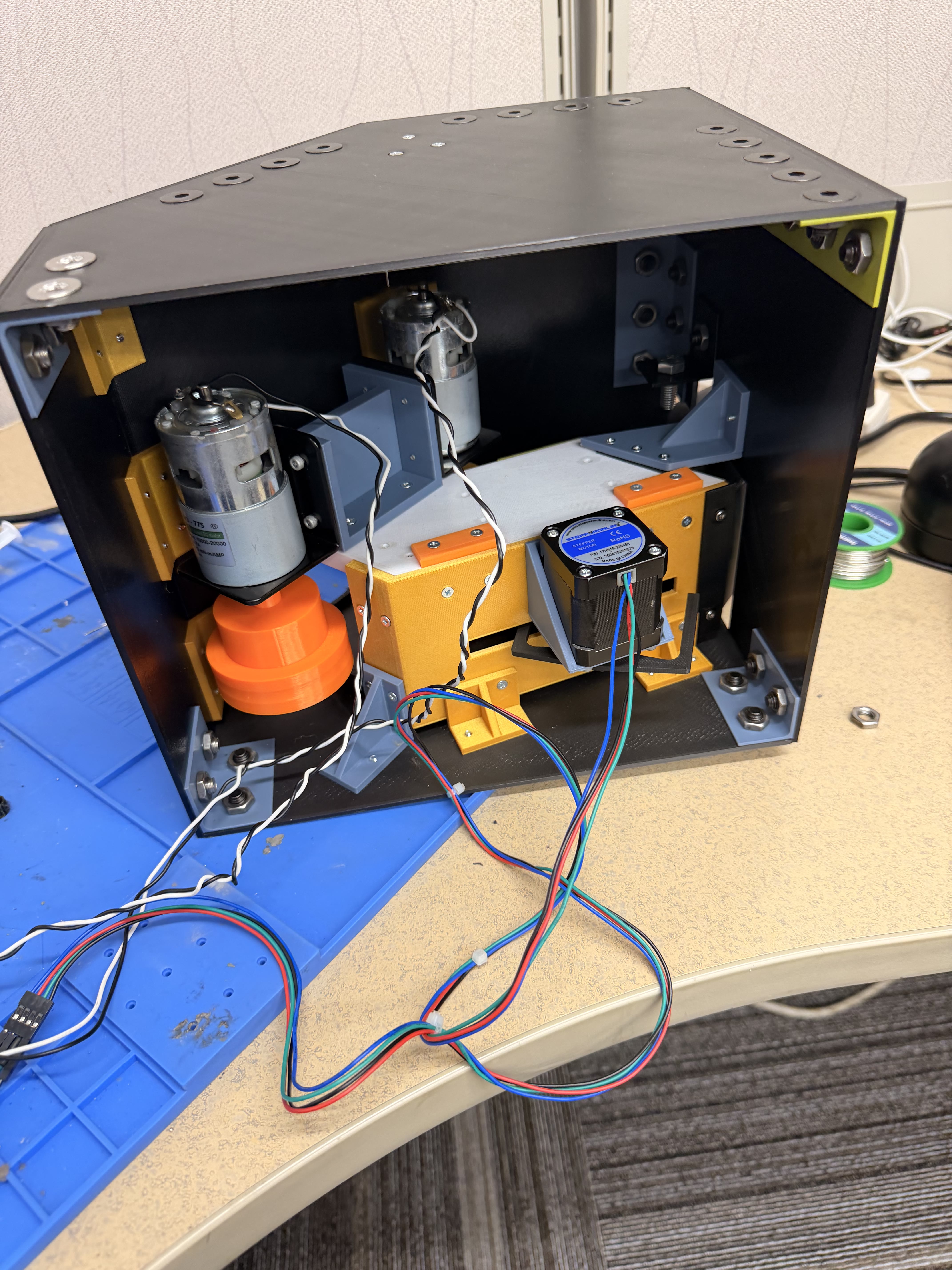
Actuator layout
Open chassis with dual RS-775 flywheels and NEMA 17 stepper

RS-775s on L-brackets with printed flywheel; NEMA 17 on the center feed stack inside the panel chassis.

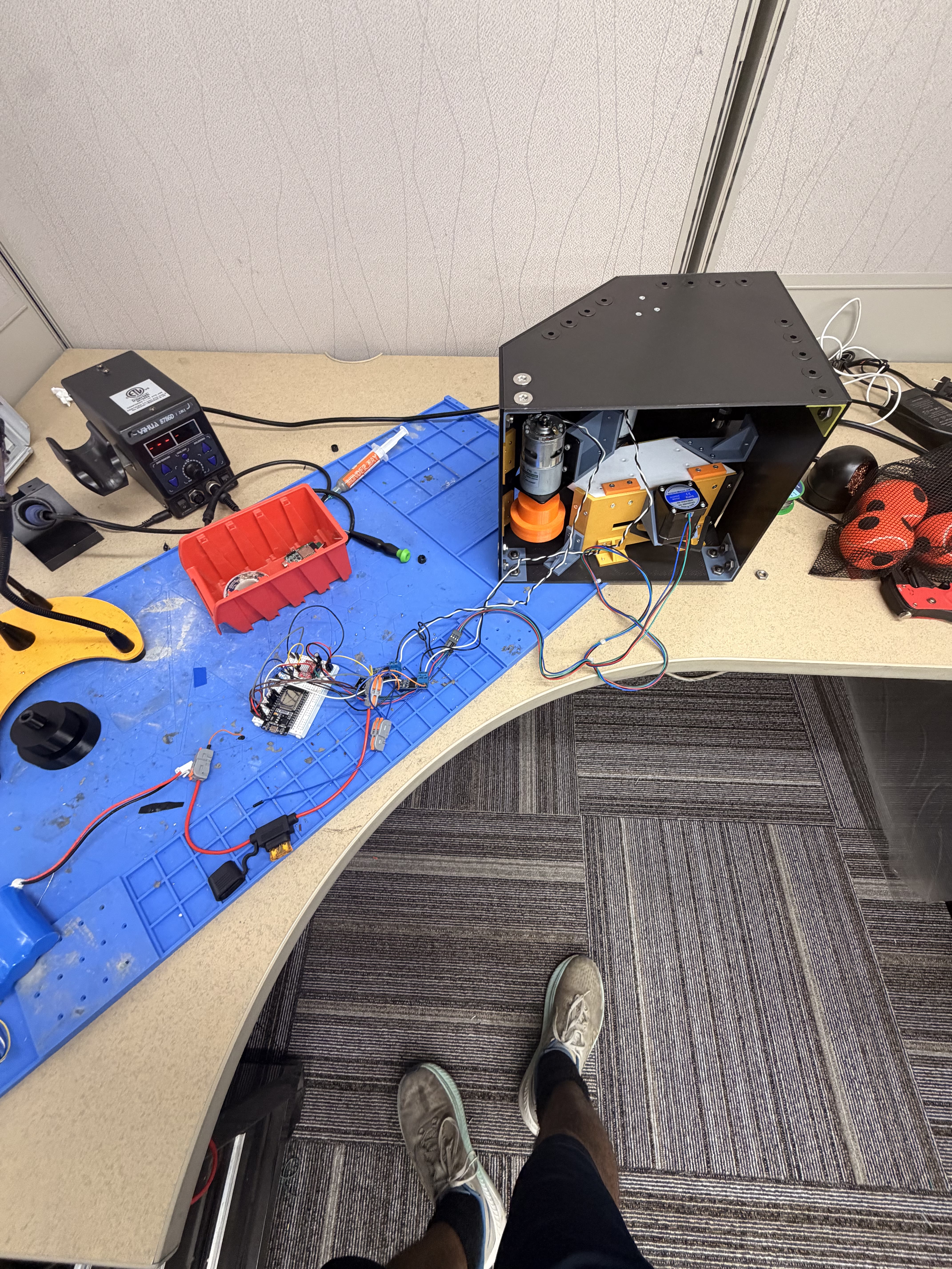
System on the bench
Chassis harnessed to ESP32 bench

Mechanical enclosure wired across to the ESP32 breadboard and fused battery path.

Debug bench
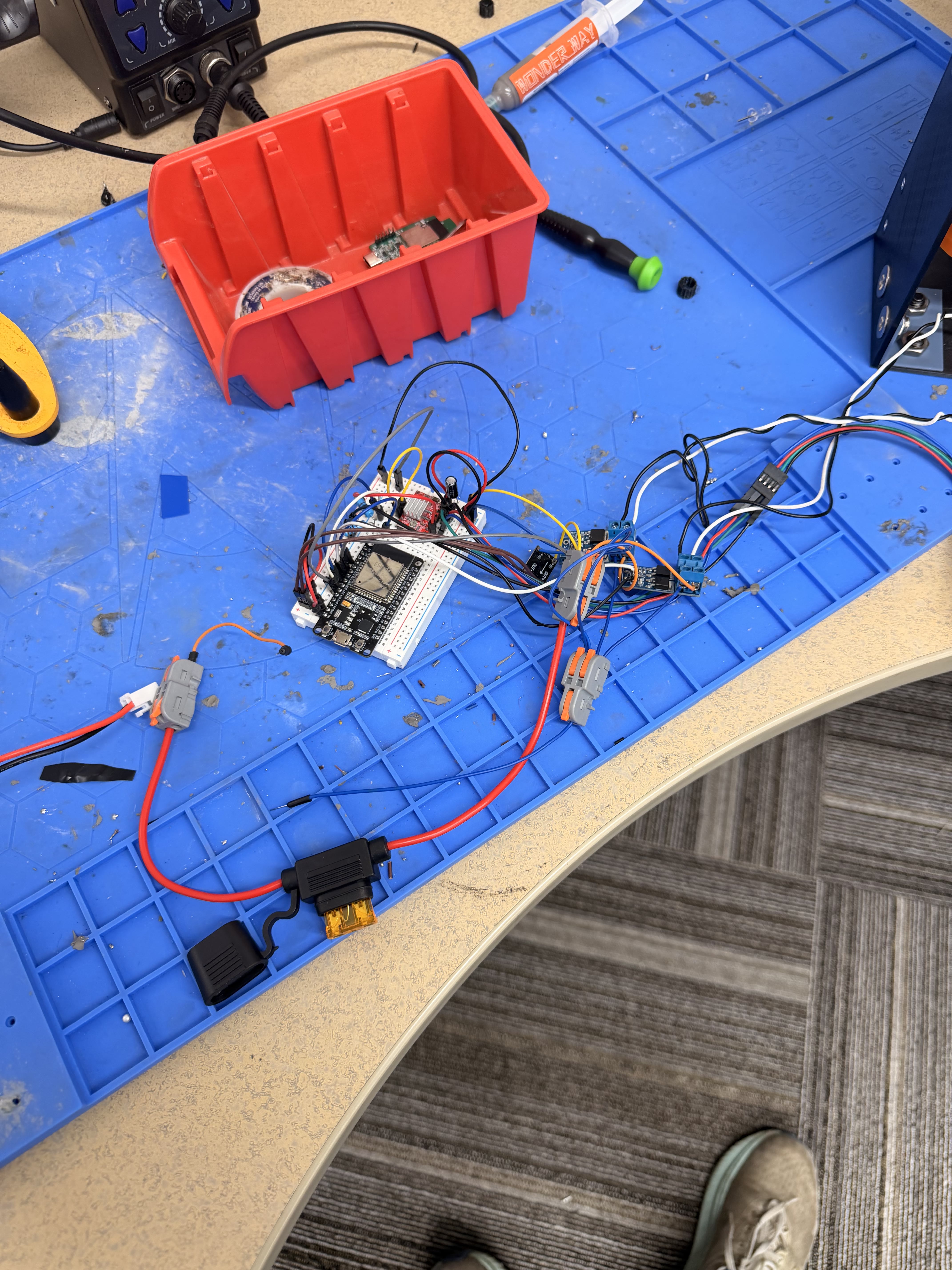
Bench layout during tennis ball shooter debugging

Bring-up mess that held the real lessons: power domains, prints, PWM, and joints before polish.

Limitations

  • Not production-ready; breadboard interface would need a custom PCB for a durable unit.
  • Fuse placement / rating did not interrupt the overspeed event the way we assumed.
  • Launcher mechanics and closed-loop current / speed sensing were not finished.
  • App integration was demo-grade, not a polished consumer UX.

Reflection

Looking back

What surprised me, what I'd redo, and questions I'm still chewing on.

What surprised me

  • The first “ESP32 is dead” bug was a missing buck converter, not firmware.
  • The first “stepper won’t index” bug was a soft print and weak fastening, not STEP/DIR timing.
  • PWM does not mean the MOSFET outputs 6 V. It means 12 V / 0 V pulses whose average the motor smooths. When that chain fails, the motor can look like it is hard-tied to the pack.
  • A fuse on the diagram is not the same as a fuse that opens when you need it. Joints failing can leave current with nowhere safe to go.

What I would redesign

  • Custom power / motor-interface PCB with deliberate fuse rating, Kelvin sense, and flyback paths.
  • Validate PWM fault modes so a stuck-high gate cannot mean continuous full pack on the flywheel.
  • Design printed feed parts for torque and fastening from revision one.
  • Add closed-loop current / speed sensing so commanded duty is not the only success signal.

Future improvements

  • PCB revision of the interface circuitry.
  • Feed reliability and launch consistency tests.
  • Packaging pass once the electrical map stops moving.

Questions that emerged

  • Which failure mode do you check first when the symptom is only “it doesn’t shoot” or “it won’t stop speeding”?
  • What fuse rating and placement actually interrupts a stuck-MOSFET fault before insulation melts?
  • What sensor proves a ball left the launcher, not just that a motor spun?