← Back to Projects
HardwareShippedFeatured

Analog Electromechanical Lightsaber

Designed and fabricated a handheld electromechanical system integrating custom mechanical packaging, discrete analog electronics, embedded lighting control, and structural design into a durable wearable prototype.

I built this in Detkin Lab as a handheld system that had to leave the breadboard. The work meant designing a custom Fusion 360 hilt, emitter, and battery carrier across multiple print revisions; integrating a discrete analog audio circuit (NE555 timer, RC network, PN2222A transistor) alongside LED blade illumination on a switched 9V power architecture; and manufacturing the boards with 40+ through-hole joints. The electronics were straightforward; the challenge was packaging them into a handheld device that could survive repeated impact and handling. Blade bending loads broke the hilt twice; cable length forced an LED pad salvage.

Engineering highlights

  • Designed a custom Fusion 360 enclosure and iterated hilt CAD/print geometry after two catastrophic impact failures under blade bending loads
  • Designed and assembled a discrete analog audio circuit using an NE555 timer, RC timing network, and PN2222A transistor to generate sound alongside LED blade illumination
  • Transitioned from breadboard validation to a soldered perfboard assembly with 40+ through-hole joints, improving durability, electrical reliability, and portability
Date
Spring 2026
Focus
Electromechanical Systems
Build stage
Shipped Demo
Disciplines
Mechanical Design · Analog Circuit Design · Electrical Integration · Manufacturing · Product Engineering
Fusion 3603D PrintingNE555PN2222APerfboardSolderingLED StripAnalog
Demo
Full write-up below. The hero is the short version. This is the build story: what I designed, what broke, and why I made the calls I did.

Motivation

Why I started this

What pulled me in, and what I wanted to get better at.

Why I built it

A friend said they made a lightsaber. I pictured a physical build; it was only CAD. That mismatch stuck. I wanted to become the kind of person who could build what I dreamed of, so I started here.

What interested me

Not the prop fantasy; the gap after a circuit works on a breadboard. Packaging, impact loads, and analog sound in one handheld object felt like real freedom as an engineer.

What I wanted to learn

Structural reliability under bending, discrete analog audio, and how manufacturing and cable length become the design once the schematic is done.

System Overview

How the system fits together

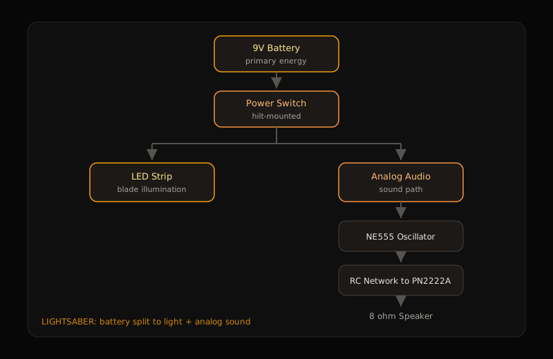
A 9V pack feeds a hilt switch, then splits. One branch lights an LED strip in the polycarbonate blade. The other is an analog audio chain: NE555 astable, RC timing, PN2222A driver, 8Ω speaker. Custom Fusion parts (hilt, emitter, battery carrier) are the load path and the harness envelope, not decoration.

01

Hilt structure

Printed geometry that must take blade bending moments and still leave room for battery, switch, and boards.

02

Power & switch

9V primary with a single hilt switch as the master enable for light and sound.

03

LED illumination

Strip inside the blade; electrically simple, mechanically constrained by lead length and strain.

04

Analog audio

NE555 + RC network for ignition/hum character; transistor stage into the speaker.

05

Manufactured boards

Breadboard validation, then point-to-point perfboard with 40+ joints before packaging.

Data flow

Battery to switch; parallel branches to LED strip and NE555; RC sets timing; PN2222A drives speaker current.

Control flow

No MCU in the loop. The switch is the control surface; frequency behavior is set by the RC network and the NE555, not firmware.

Power split
Lightsaber power and analog audio block diagram

Battery and switch, then parallel LED and NE555 audio paths.

Engineering Breakdown

Broken down by discipline

Each block covers the goal, the design, what broke, what changed, and what shipped.

01Mechanical

Mechanical

Goal

A hilt that packages the electronics and survives repeated impact without losing alignment of the internals.

Design

Custom hilt, emitter, and battery holder in Fusion 360, printed around the real electrical envelope rather than around a pretty silhouette.

Challenges

  • Two catastrophic hilt failures during lightsaber impacts. Early instinct blamed a weak print; the load case was the real issue.
  • The polycarbonate blade is a long lever. Force at the tip concentrates bending moment at the printed hilt root.
  • The schematic never failed under those hits; the packaging did. Stronger glue would have masked a bad load path.

Iterations

  • Failure inspection on the fracture surfaces and how the blade loaded the hilt.
  • CAD redesign with more structural reinforcement around the root and emitter interface.
  • Print settings changed: higher infill and thicker walls where the bending moment peaked.

Final implementation

Redesigned assembly held through repeated impacts while keeping battery, boards, and switch aligned inside the hilt.

CAD design

Hilt and emitter geometry sized to electronics and to bending loads, not just fitment.
02Electrical

Electrical

Goal

Integrate a simple lighting circuit into a handheld package without creating a fragile service joint.

Design

9V through the hilt switch into the LED strip. Electrically short; the hard work was lead length, routing, and strain once the hilt closed.

Challenges

  • After final assembly, one LED strip lead was too short to reach the switch. No spare strips on hand.
  • Rebuilding the CAD around a longer lead would have burned a working packaging cycle. I modified the strip instead.
  • Exposed copper pads inside the strip and soldered to them. Pads are tiny and not meant for repeated mechanical load; the first joint failed when the cable moved.

Iterations

  • Pad exposure and first solder attempt under magnification-level care.
  • Mechanical failure of the joint under cable pull.
  • Strain relief and tape reinforcement until the joint survived repeated handling.

Final implementation

Salvaged strip stayed in the final build. Lighting works without a replacement part or a second enclosure spin.

LED pad salvage

Pad-level solder and strain relief after the strip lead came up short in the closed hilt.

03Analog Circuit Design

Analog Circuit Design

Goal

Ignition and continuous hum from discrete analog parts; no microcontroller audio path.

Design

NE555 as an astable oscillator. RC network sets the timing character. PN2222A amplifies into an 8Ω speaker.

Challenges

  • Textbook RC math predicted a much longer frequency sweep than the hardware produced.
  • Speaker response and NE555 nonidealities made the ear the better instrument than the first calculation.
  • Component tolerances showed up as character change, not as a clean scale factor on the formula.

Iterations

  • Breadboard RC sweeps against what the speaker actually rendered.
  • Adjust timing network until ignition and hum read as intentional, not as a random square wave.
  • Transfer the working network to perfboard without losing the tuned behavior.

Final implementation

Packaged analog chain runs inside the closed hilt and produces recognizable ignition and hum. Theory framed the design; measurement closed it.

Analog circuit alone

NE555 path on the supply by itself; sound character without the hilt in the loop.

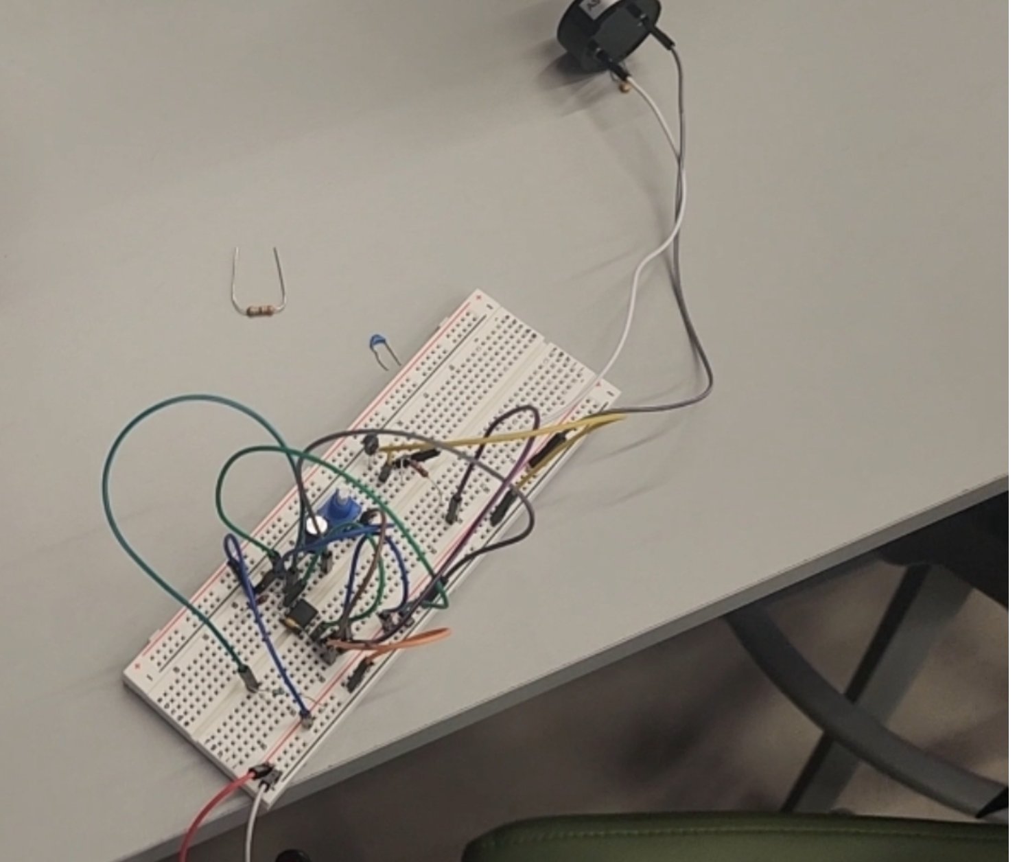
Breadboard bring-up
Breadboard analog audio circuit for the lightsaber

RC network tuned against real speaker behavior before freezing the design.

04Manufacturing

Manufacturing

Goal

Move from a floating prototype to a reworkable, soldered assembly that fits the printed envelope.

Design

Breadboard for validation, manual transfer to perfboard, then integrate into the printed housing. Point-to-point wiring; no custom PCB for this revision.

Challenges

  • 40+ through-hole joints; each one is a future failure site if the joint is cold or the lead has no strain path.
  • Perfboard layout had to match hilt volume, not a generous bench footprint.
  • Every packaging change threatened a previously good solder joint.

Iterations

  • Breadboard proof of light and sound.
  • Perfboard transfer with continuity checks before closing the hilt.
  • Multiple packaging fits before the harness lengths stopped fighting the CAD.

Final implementation

Soldered audio and power distribution inside the printed assembly; joints that survive handling once the hilt closes.

Perfboard permanence
Perfboard analog audio circuit for the lightsaber

Point-to-point assembly after breadboard validation; 40+ joints sized for the hilt envelope.

05Product Engineering

Product Engineering

Goal

One handheld object where structure, power, light, and sound share constraints without constant teardown.

Design

Co-design loop: CAD envelope, board size, cable lengths, and switch reach were negotiated together. Integration was the product.

Challenges

  • A working breadboard lied about clearance and lead length.
  • Mechanical redesigns after impact failure forced electrical re-routing.
  • Salvaged LED joint had to stay reliable after the hilt was closed.

Iterations

  • Separate bring-up of light and sound.
  • First packaged assembly and impact failures.
  • Structural redesign, LED salvage, final closed hilt.

Final implementation

Assembled lightsaber with illumination, analog sound, and a hilt that takes repeated hits after the redesign.

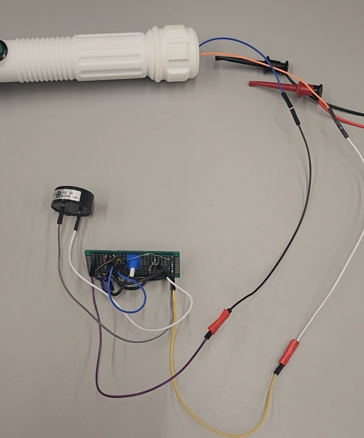
Circuit in the saber

Discrete analog board alive inside the packaged hilt; light and sound as one object.

Key Design Decisions

Calls I actually made

What else was on the table, what I picked, and why it still made sense once the hardware was real.

01

Analog audio instead of microcontroller playback

The problem

Need ignition and hum without turning the project into a firmware demo.

Alternatives considered

  • Arduino or MCU with sample playback
  • NE555 + RC + transistor driver

Tradeoffs

MCU audio is flexible and hides oscillator design. Discrete analog forces timing networks, drive current, and speaker limits into the open.

Why I chose this

Analog path. The learning target was oscillator behavior and board-level audio, not WAV playback.

02

Custom CAD enclosure over a generic tube

The problem

Off-the-shelf hilts fight battery placement, switch reach, and board volume.

Alternatives considered

  • Generic tube or kit hilt
  • Custom Fusion hilt, emitter, battery carrier

Tradeoffs

Generic is faster day one. Custom costs print cycles; it buys a load path and cable routes you can redesign after failure.

Why I chose this

Custom CAD. Packaging and structural rigidity were design variables, not afterthoughts.

03

Redesign the housing instead of stronger adhesive

The problem

Hilt failed twice under impact at the blade root.

Alternatives considered

  • More glue / clamp force
  • Geometry and print-parameter redesign from the bending load case

Tradeoffs

Adhesive can hold a bad interface for a demo. It does not fix a lever arm concentrating moment into weak plastic.

Why I chose this

Treat it as failure analysis. Change geometry and infill where the moment peaks.

04

Perfboard instead of jumping straight to a PCB

The problem

Need permanence past Duponts while the hilt envelope was still moving.

Alternatives considered

  • Stay on breadboard
  • Perfboard point-to-point
  • Custom PCB

Tradeoffs

Breadboard lies under motion. PCB is right when connectors freeze. Perfboard is temporary permanence.

Why I chose this

Perfboard with 40+ joints. Enough reliability to package; flexible enough for one more mechanical spin.

05

Solder to LED strip pads instead of redesigning for a new strip

The problem

Lead too short after assembly; no replacement strip available.

Alternatives considered

  • Wait for a new strip and reprint routing
  • Expose strip pads and extend with solder + strain relief

Tradeoffs

Replacement is cleaner electrically. Salvage is uglier and more delicate; it keeps the packaging cycle alive under a hard constraint.

Why I chose this

Pad solder plus strain relief. Resourcefulness under part scarcity was the engineering move.

Evolution

How it got here

Bench bring-up, CAD fits, soldering, and the demos in between. Not just the final photo.

  1. Concept

    Whiteboard and breadboard

    Circuit sketch and first power-on for light and sound before any hilt geometry was trusted.

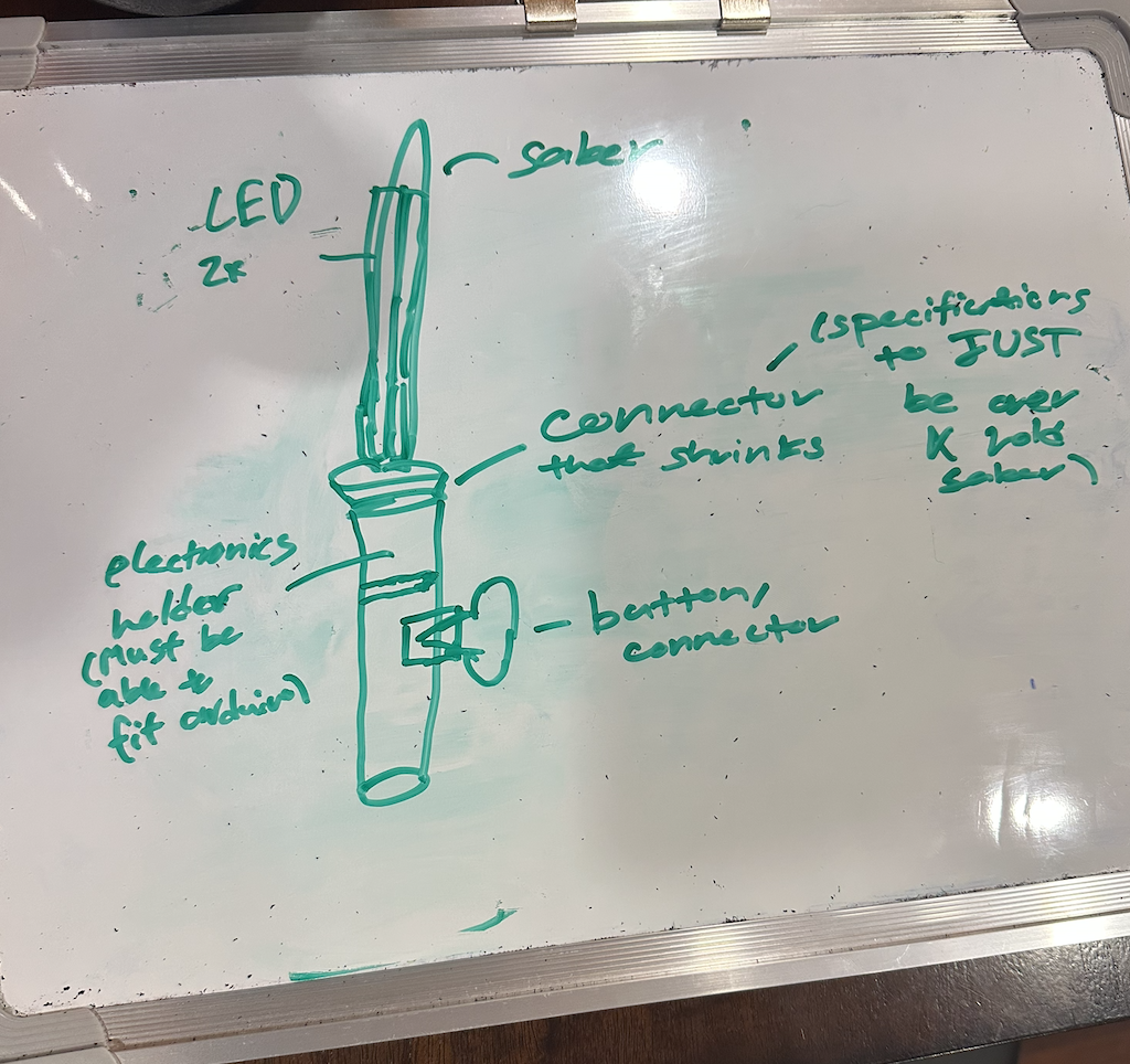
    Whiteboard
    Whiteboard planning for the lightsaber

    Plan before the first print assumed the load case was kind.

  2. Analog

    Sound circuit on the bench

    NE555 path tuned on breadboard against what the speaker actually produced, not against the first RC estimate.

    Audio bring-up
    Breadboard audio bring-up

    Where theory and the ear disagreed.

  3. CAD v1

    First printed enclosure

    Initial hilt and emitter prints packaged the boards. Fit looked fine until impact testing started.

    CAD v1

    Geometry before the bending-moment lesson.

  4. Failure

    Two hilt failures under impact

    Blade tip loads showed up as root fractures. That is when the lever-arm story replaced the weak-print story.

    No media for this milestone yet.
  5. Structure

    CAD and print redesign

    Reinforced root geometry; infill and wall thickness raised where the moment peaked. Same electronics, different load path.

    No media for this milestone yet.
  6. Permanence

    Perfboard and LED salvage

    Audio moved to perfboard. Short LED lead forced pad-level soldering and strain relief instead of a parts swap.

    Perfboard
    Perfboard audio circuit

    Joints meant to survive the closed hilt.

  7. Ship

    Final handheld assembly

    Closed unit with light, analog sound, and a hilt that takes hits after the redesign. Lab checkout closed the loop.

    Final demo

    Integrated system on the redesigned structure.

Results & Validation

What held up

What worked in the end, what I can show for it, and where it's still limited.

Impact durability after redesign

Impact retest

Post-redesign hilt survived repeated blade impacts that had previously caused two catastrophic failures.

Illumination

Functional light

LED strip lights the blade from the packaged 9V path, including the salvaged pad joint.

Analog sound

Functional audio

Ignition and continuous hum from the NE555 chain on the handheld unit.

Integrated packaging

Closed assembly

Battery, switch, boards, and speaker inside custom printed parts; not a breadboard in a shell.

Manufacturing volume

0+ joints; CAD revs

40+ through-hole joints across the power and audio path; multiple CAD revisions driven by failure analysis.

Photos and clips

The runs and stills that match the results above.

Validation demo

Light and sound on the assembled unit after the structural redesign.

Whiteboard plan
Whiteboard circuit and hilt planning sketch

Early mechanical and electrical layout before print iterations.

Airport bit

Not evidence. Just me taking the blade through the airport; funny travel still, zero engineering substance.

Limitations

  • Analog character is fixed in hardware; no runtime tone profiles.
  • Pad-soldered LED joint is robust enough for use; it is still a scar from a packaging miss.
  • 9V alkaline path is simple and heavy; battery optimization is a next revision, not this one.

Reflection

Looking back

What surprised me, what I'd redo, and questions I'm still chewing on.

What surprised me

  • The electrical schematic was the easy part. Mechanical packaging, structural loading, manufacturability, and integration decided whether the project worked.
  • I underestimated bending loads until the hilt failed twice; the blade as a lever arm was obvious only after the fractures.
  • Salvaging the LED strip under a hard parts constraint taught more about hardware debugging than a clean reorder would have.

What I would redesign

  • Design cable reach and service loops before freezing CAD.
  • Add intentional flex relief at every pad-level repair.
  • Consider a small PCB once the hilt envelope stops moving.

Future improvements

  • Lighter power architecture without losing the analog sound path.
  • Cleaner internal harness with keyed connectors for rework.
  • Blade interface designed explicitly as a bending member from revision one.

Questions that emerged

  • When does custom CAD stop being freedom and start being the only honest way to learn load paths?
  • How do you budget packaging risk when the schematic looks finished?
  • What should a first hardware project optimize for: features, or surviving contact with the real world?